Note : Les descriptions sont présentées dans la langue officielle dans laquelle elles ont été soumises.
VEHICLE ACTIVATION SYSTEMS AND METHODS FOR ELECTRIC VEHICLES
CROSS-REFERENCE TO RELATED APPLICATION
[0001] This application claims priority from U.S. Provisional Patent
Application
No. 63/193,241, filed May 26, 2021.
TECHNICAL FIELD
[0002] The disclosure relates generally to electric vehicles, and
more particularly
to activating electric vehicles.
BACKGROUND
[0003] Vehicles that have an internal combustion engine are
typically provided
with an ignition switch or button that is used to activate a starter motor
that in turn causes
the engine to start. The operator can typically perceive that the engine has
started and
the vehicle is ready to be driven when the sound of the engine can be heard.
Compared
to vehicles with internal combustion engines, electric vehicles are typically
more quiet and
the lack of internal combustion engine sound can make the state of the
electric vehicle
less readily perceivable during start-up. Improvement is desirable.
SUMMARY
[0004] In one aspect, the disclosure describes a method of
activating an electric
vehicle. The method comprises:
when the electric vehicle is in an inactive state, receiving, via an operator
input device disposed on the electric vehicle, a first command to activate the
electric
vehicle;
in response to the first command, transitioning the electric vehicle from the
inactive state to a wake state where a controller of the electric vehicle is
activated and
the electric vehicle is prevented from being propelled by an electric motor
configured to
propel the electric vehicle;
after receiving the first command, receiving, via the operator input device,
a second command to activate the electric vehicle when a shutoff switch of the
electric
vehicle is in a vehicle-on configuration; and
-1 -
Date Recue/Date Received 2022-09-20
in response to the second command, transitioning the electric vehicle from
the wake state to a ready state where the electric vehicle is permitted to be
propelled by
the electric motor.
[0005] The method may comprise, in response to the first command,
providing a
first visual indication of a first color indicating the wake state of the
electric vehicle.
[0006] The method may comprise, in response to the second command,
providing a second visual indication of a second color indicating the ready
state of the
electric vehicle.
[0007] The first and second visual indications may include an
illumination of an
instrument panel of the electric vehicle.
[0008] The method may comprise changing the second color of the
second visual
indication when transitioning the electric vehicle from a forward mode of
operation to a
reverse mode of operation.
[0009] Transitioning the electric vehicle from the inactive state to
the wake state
may include electrically connecting a battery to an inverter operatively
connected to
control a delivery of electric power from the battery to the electric motor.
[0010] Transitioning the electric vehicle from the inactive state to
the wake state
may include charging a capacitor electrically connected in parallel with the
inverter.
[0011] The method may comprise:
after receiving the first command and before receiving the second
command, receiving, via the operator input device, another command to activate
the
electric vehicle when the shutoff switch is in a vehicle-off configuration;
and
in response to the other command, alerting an operator of the electric
vehicle.
[0012] Alerting the operator may include producing an audible indication.
[0013] Transitioning the electric vehicle from the wake state to the
ready state
may be conditioned upon an operator's authorization to operate the electric
vehicle
having been received.
- 2 -
Date Recue/Date Received 2022-04-07
[0014] The method may comprise:
ignoring one or more first accelerator commands received via an
accelerator of the electric vehicle when the electric vehicle is in the wake
state; and
executing one or more second accelerator commands received via the
accelerator when the electric vehicle is in the ready state.
[0015] The method may comprise:
after receiving the second command, receiving a third command from the
operator input device; and
in response to the third command, transitioning the electric vehicle from
the ready state to the wake state.
[0016] The operator input device may include a push button via which
the first
and second commands are received.
[0017] The method may comprise, when the electric vehicle is in the
wake state
and is in motion causing back-driving of the electric motor, causing
regenerative braking
of the electric motor.
[0018] Embodiments may include combinations of the above features.
[0019] In another aspect, the disclosure describes a computer
program product
for operating an electric vehicle, the computer program product comprising a
non-
transitory computer readable storage medium having program code embodied
therewith,
the program code readable/executable by a computer, processor or logic circuit
to
perform a method as described herein.
[0020] In another aspect, the disclosure describes a vehicle
activation system for
an electric vehicle. The vehicle activation system comprises:
an operator input device for receiving a first command and a second
command to activate the electric vehicle;
a shutoff switch configurable between a vehicle-on configuration and a
vehicle-off configuration;
- 3 -
Date Recue/Date Received 2022-04-07
one or more data processors operatively connected to the operator input
device and to the shutoff switch; and
non-transitory machine-readable memory storing instructions executable
by the one or more data processors and configured to cause the one or more
data
processors to:
in response to receiving the first command to activate the electric vehicle,
cause the electric vehicle to be prevented from being propelled by an electric
motor
configured to propel the electric vehicle; and
in response to receiving the second command to activate the electric
vehicle after receiving the first command and when the shutoff switch is in
the vehicle-on
configuration, cause the electric vehicle to be permitted to be propelled by
the electric
motor.
[0021] The instructions may be configured to cause the one or more
data
processors to, in response to the first command, cause a first visual
indication of a first
color to be provided.
[0022] The instructions may be configured to cause the one or more
data
processors to, in response to the second command, cause a second visual
indication of
a second color different from the first color to be provided.
[0023] The first and second visual indications may include an
illumination of an
instrument panel of the electric vehicle.
[0024] The instructions may be configured to cause the one or more
data
processors to cause the second color of the second visual indication to be
changed when
the electric vehicle is transitioned from a forward mode of operation to a
reverse mode of
operation.
[0025] The instructions may be configured to cause the one or more data
processors to, in response to the first command, cause a battery of the
electric vehicle to
be electrically connected to a power electronics module configured to control
a delivery
of electric power from the battery to the electric motor.
- 4 -
Date Recue/Date Received 2022-04-07
[0026] The instructions may be configured to cause the one or more
data
processors to, in response to the first command, cause charging of a capacitor
of the
power electronics module.
[0027] The instructions may be configured to cause the one or more
data
processors to cause an alert to be generated in response to another command to
activate
the electric vehicle being received after receiving the first command, before
receiving the
second command and when the shutoff switch of the electric vehicle is in the
vehicle-off
configuration.
[0028] The alert may include an audible indication.
[0029] The second command may be configured to cause the electric vehicle
to
be permitted to be propelled by the electric motor conditioned upon an
operator's
authorization to operate the electric vehicle being received.
[0030] The instructions may be configured to cause the one or more
data
processors to, in response to receiving a third command via the operator input
device
after receiving the second command, cause the electric vehicle to be prevented
from
being propelled by the electric motor.
[0031] The operator input device may include a push button via which
the first
and second commands are received.
[0032] The instructions may be configured to cause the one or more
data
processors to, after receiving the first command, before receiving the second
command,
and when the electric vehicle is in motion causing back-driving of the
electric motor, cause
regenerative braking of the electric motor.
[0033] Embodiments may include combinations of the above features.
[0034] In another aspect, the disclosure describes an electric
powersport vehicle
comprising a vehicle activation system as described herein.
[0035] In another aspect, the disclosure describes an electric
snowmobile
comprising a vehicle activation system as described herein.
[0036] In another aspect, the disclosure describes an electric
powersport vehicle
comprising:
- 5 -
Date Recue/Date Received 2022-04-07
an electric motor configured to propel the electric powersport vehicle;
an operator input device for receiving a first command and a second
command to activate the electric powersport vehicle;
a shutoff switch configurable between a vehicle-on configuration and a
vehicle-off configuration; and
a controller operatively connected to the electric motor, to the operator
input device, and to the shutoff switch, the controller being configured to:
in response to the first command to activate the electric powersport vehicle
being received via the operator input device, cause the electric powersport
vehicle to be
prevented from being propelled by the electric motor; and
in response to the second command to activate the electric powersport
vehicle being received via the operator input device after receiving the first
command and
when the shutoff switch is in the vehicle-on configuration, cause the electric
powersport
vehicle to be permitted to be propelled by the electric motor.
[0037] The controller may be configured to, in response to the first
command,
cause a visual indication to be provided.
[0038] The controller may be configured to, in response to the
second command,
cause a color of the visual indication to be changed.
[0039] The visual indication may include an illumination of an
instrument panel of
the electric powersport vehicle.
[0040] The controller may be configured to:
cause the visual indication to have a first color when the electric
powersport vehicle is in a forward mode of operation; and
cause the visual indication to have a second color different from the first
color when the electric powersport vehicle is in a reverse mode of operation.
[0041] The controller may be configured to, in response to the first
command,
cause a battery of the electric powersport vehicle to be electrically
connected to a power
- 6 -
Date Recue/Date Received 2022-04-07
electronics module configured to control a delivery of electric power from the
battery to
the electric motor.
[0042] The controller may be configured to, in response to the first
command,
cause charging of a capacitor of the power electronics module.
[0043] The controller may be configured to cause an alert to be generated
in
response to another command to activate the electric powersport vehicle being
received
after receiving the first command, before receiving the second command and
when the
shutoff switch of the electric powersport vehicle is in the vehicle-off
configuration.
[0044] The alert may include an audible indication.
[0045] The second command may be configured to cause the electric
powersport
vehicle to be permitted to be propelled by the electric motor conditioned upon
an
operator's authorization to operate the electric powersport vehicle being
received.
[0046] The controller may be configured to, in response to receiving
a third
command via the operator input device after receiving the second command,
cause the
electric powersport vehicle to be prevented from being propelled by the
electric motor.
[0047] The operator input device may include a push button via which
the first
and second commands are received.
[0048] The push button may be disposed at a location other than on a
handlebar
of the electric powersport vehicle.
[0049] The controller may be configured to, after receiving the first
command,
before receiving the second command, and when the electric powersport vehicle
is in
motion causing back-driving of the electric motor, cause regenerative braking
of the
electric motor.
[0050] Embodiments may include combinations of the above features.
[0051] In another aspect, the disclosure describes a method of activating
an
electric powersport vehicle. The method comprises:
- 7 -
Date Recue/Date Received 2022-04-07
when the electric powersport vehicle is in an inactive state, receiving, via
a push button disposed on the electric powersport vehicle, a first command to
activate
the electric powersport vehicle;
in response to the first command, transitioning the electric powersport
vehicle from the inactive state to a wake state where a controller of the
electric powersport
vehicle is activated and the electric powersport vehicle is prevented from
being propelled
by an electric motor configured to propel the electric powersport vehicle;
after receiving the first command, receiving, via the push button, a second
command to activate the electric powersport vehicle; and
in response to the second command, transitioning the electric powersport
vehicle from the wake state to a ready state where the electric powersport
vehicle is
permitted to be propelled by the electric motor.
[0052] The method may comprise, in response to the first command,
providing a
first visual indication of a first color indicating the wake state of the
electric powersport
.. vehicle.
[0053] The method may comprise, in response to the second command,
providing a second visual indication of a second color indicating the ready
state of the
electric powersport vehicle.
[0054] The first and second visual indications may include an
illumination of an
instrument panel of the electric powersport vehicle.
[0055] The method may comprise changing the second color of the
second visual
indication when transitioning the electric powersport vehicle from a forward
mode of
operation to a reverse mode of operation.
[0056] Transitioning the electric powersport vehicle from the
inactive state to the
wake state may include electrically connecting a battery to an inverter
operatively
connected to control a delivery of electric power from the battery to the
electric motor.
[0057] Transitioning the electric powersport vehicle from the
inactive state to the
wake state may include charging a capacitor electrically connected in parallel
with the
inverter.
- 8 -
Date Recue/Date Received 2022-04-07
[0058] Transitioning the electric powersport vehicle from the wake
state to the
ready state may be conditioned upon an operator's authorization to operate the
electric
powersport vehicle having been received.
[0059] The method may comprise: after receiving the second command,
receiving a third command from the push button; and in response to the third
command,
transitioning the electric powersport vehicle from the ready state to the wake
state.
[0060] The method may comprise, when the electric powersport vehicle
is in the
wake state and is in motion causing back-driving of the electric motor,
causing
regenerative braking of the electric motor.
[0061] Embodiments may include combinations of the above features.
[0062] In another aspect, the disclosure describes an electric
powersport vehicle
comprising:
an electric motor configured to propel the electric powersport vehicle;
a push button for receiving a first command and a second command to
activate the electric powersport vehicle; and
a controller operatively connected to the electric motor and to the push
button, the controller being configured to:
in response to the first command to activate the electric powersport vehicle
being received via the push button, cause the electric powersport vehicle to
be prevented
from being propelled by the electric motor; and
in response to the second command to activate the electric powersport
vehicle being received via the push button after receiving the first command,
cause the
electric powersport vehicle to be permitted to be propelled by the electric
motor.
[0063] The controller may be configured to, in response to the first
command,
cause a first visual indication of a first color to be provided.
[0064] The controller may be configured to, in response to the
second command,
cause a second visual indication of a second color different from the first
color to be
provided.
- 9 -
Date Recue/Date Received 2022-04-07
[0065] The first and second visual indications may include an
illumination of an
instrument panel of the electric powersport vehicle.
[0066] The controller may be configured to cause the second color of
the second
visual indication to be changed when the electric powersport vehicle is
transitioned from
a forward mode of operation to a reverse mode of operation.
[0067] The controller may be configured to, in response to the first
command,
cause a battery of the electric powersport vehicle to be electrically
connected to a power
electronics module configured to control a delivery of electric power from the
battery to
the electric motor.
[0068] The controller may be configured to, in response to the first
command,
cause charging of a capacitor of the power electronics module.
[0069] The second command may be configured to cause the electric
powersport
vehicle to be permitted to be propelled by the electric motor conditioned upon
an
operator's authorization to operate the electric powersport vehicle being
received.
[0070] The controller may be configured to, in response to receiving a
third
command via the push button after receiving the second command, cause the
electric
powersport vehicle to be prevented from being propelled by the electric motor.
[0071] The controller may be configured to, after receiving the
first command,
before receiving the second command, and when the electric powersport vehicle
is in
motion causing back-driving of the electric motor, cause regenerative braking
of the
electric motor.
[0072] The push button may be disposed at a location other than on a
handlebar
of the electric powersport vehicle.
[0073] The electric powersport vehicle may be a snowmobile.
[0074] Embodiments may include combinations of the above features.
[0075] In another aspect, the disclosure describes a method of
activating an
electric vehicle including an electric motor configured to propel the electric
vehicle using
electric power from a battery. The method comprises:
- 10 -
Date Recue/Date Received 2022-04-07
when the electric vehicle is in an inactive state, receiving, via an operator
input device disposed on the electric vehicle, a first command to activate the
electric
vehicle;
in response to the first command, transitioning the electric vehicle from the
inactive state to a wake state where:
a controller of the electric vehicle is activated;
a capacitor of a power electronics module operatively disposed between
the battery and the electric motor is charged; and
the electric vehicle is prevented from being propelled by the electric motor;
after receiving the first command, receiving, via the operator input device,
a second command to activate the electric vehicle; and
in response to the second command, transitioning the electric vehicle from
the wake state to a ready state where the electric vehicle is permitted to be
propelled by
the electric motor.
[0076] The method may comprise, in response to the first command, providing
a
first visual indication of a first color indicating the wake state of the
electric vehicle.
[0077] The method may comprise, in response to the second command,
providing a second visual indication of a second color indicating the ready
state of the
electric vehicle.
[0078] The first and second visual indications may include an illumination
of an
instrument panel of the electric vehicle.
[0079] The method may comprise changing the second color of the
second visual
indication when transitioning the electric vehicle from a forward mode of
operation to a
reverse mode of operation.
[0080] Transitioning the electric vehicle from the wake state to the ready
state
may be conditioned upon an operator's authorization to operate the electric
vehicle
having been received.
-11 -
Date Recue/Date Received 2022-04-07
[0081] The method may comprise: after receiving the second command,
receiving a third command from the operator input device; and in response to
the third
command, transitioning the electric vehicle from the ready state to the wake
state.
[0082] The method may comprise, when the electric vehicle is in the
wake state
and is in motion causing back-driving of the electric motor, causing
regenerative braking
of the electric motor.
[0083] Embodiments may include combinations of the above features.
[0084] In another aspect, the disclosure describes a vehicle
activation system for
an electric vehicle. The vehicle activation system comprises:
an operator input device for receiving a first command and a second
command to activate the electric vehicle;
one or more data processors operatively connected to the operator input
device; and
non-transitory machine-readable memory storing instructions executable
by the one or more data processors and configured to cause the one or more
data
processors to:
in response to receiving the first command to activate the electric vehicle:
cause a capacitor of a power electronics module operatively disposed
between a battery and an electric motor configured to propel the electric
vehicle to be
charged; and
cause the electric vehicle to be prevented from being propelled by the
electric motor; and
in response to receiving the second command to activate the electric
vehicle after receiving the first command, cause the electric vehicle to be
permitted to be
propelled by the electric motor.
[0085] The instructions may be configured to cause the one or more
data
processors to, in response to the first command, cause a first visual
indication of a first
color to be provided.
- 12 -
Date Recue/Date Received 2022-04-07
[0086] The instructions may be configured to cause the one or more
data
processors to, in response to the second command, cause a second visual
indication of
a second color different from the first color to be provided.
[0087] The first and second visual indications may include an
illumination of an
instrument panel of the electric vehicle.
[0088] The instructions may be configured to cause the one or more
data
processors to cause the second color of the second visual indication to be
changed when
the electric vehicle is transitioned from a forward mode of operation to a
reverse mode of
operation.
[0089] The second command may be configured to cause the electric vehicle
to
be permitted to be propelled by the electric motor conditioned upon an
operator's
authorization to operate the electric vehicle being received.
[0090] The instructions may be configured to cause the one or more
data
processors to, in response to receiving a third command via the operator input
device
after receiving the second command, cause the electric vehicle to be prevented
from
being propelled by the electric motor.
[0091] The instructions may be configured to cause the one or more
data
processors to, after receiving the first command, before receiving the second
command,
and when the electric vehicle is in motion causing back-driving of the
electric motor, cause
regenerative braking of the electric motor.
[0092] Embodiments may include combinations of the above features.
[0093] In another aspect, the disclosure describes an electric
powersport vehicle
comprising:
an electric motor configured to propel the electric powersport vehicle;
a battery for supplying electric power to the electric motor;
a power electronics module operatively connected between the battery
and the electric motor;
- 13 -
Date Recue/Date Received 2022-04-07
an operator input device for receiving a first command and a second
command to activate the electric powersport vehicle; and
a controller operatively connected to the operator input device and to the
power electronics module, the controller being configured to:
in response to the first command to activate the electric powersport vehicle
being received via the operator input device when the electric powersport
vehicle is in an
inactive state:
cause a capacitor of the power electronics module to be charged; and
cause the electric powersport vehicle to be prevented from being propelled
by the electric motor; and
in response to the second command to activate the electric powersport
vehicle being received via the operator input device after receiving the first
command,
cause the electric powersport vehicle to be permitted to be propelled by the
electric motor.
[0094] The controller may be configured to, in response to the first
command,
cause a first visual indication of a first color to be provided.
[0095] The controller may be configured to, in response to the
second command,
cause a second visual indication of a second color different from the first
color to be
provided.
[0096] The first and second visual indications may include an
illumination of an
instrument panel of the electric powersport vehicle.
[0097] The controller may be configured to cause the second color of
the second
visual indication to be changed when the electric powersport vehicle is
transitioned from
a forward mode of operation to a reverse mode of operation.
[0098] The second command may be configured to cause the electric
powersport
vehicle to be permitted to be propelled by the electric motor conditioned upon
an
operator's authorization to operate the electric powersport vehicle being
received.
- 14 -
Date Recue/Date Received 2022-04-07
[0099]
The controller may be configured to, in response to receiving a third
command via the operator input device after receiving the second command,
cause the
electric powersport vehicle to be prevented from being propelled by the
electric motor.
[00100]
The controller may be configured to, after receiving the first command,
before receiving the second command, and when the electric powersport vehicle
is in
motion causing back-driving of the electric motor, cause regenerative braking
of the
electric motor.
[00101]
The operator input device may be disposed at a location other than on a
handlebar of the electric powersport vehicle.
[00102] Embodiments may include combinations of the above features.
[00103] In
another aspect, the disclosure describes a method of activating an
electric vehicle. The method comprises:
when the electric vehicle is in an inactive state, receiving a first command
to activate the electric vehicle;
in response to the first command, transitioning the electric vehicle from the
inactive state to a wake state where:
a controller of the electric vehicle is activated;
the electric vehicle is prevented from being propelled by an electric motor
configured to propel the electric vehicle; and
regenerative braking of the electric motor is caused when the electric
vehicle is in motion causing back-driving of the electric motor;
after receiving the first command, receiving a second command to activate
the electric vehicle; and
in response to the second command, transitioning the electric vehicle from
the wake state to a ready state where the electric vehicle is permitted to be
propelled by
the electric motor.
[00104]
The method may comprise, in response to the first command, providing a
first visual indication of a first color indicating the wake state of the
electric vehicle.
- 15 -
Date Recue/Date Received 2022-04-07
[00105] The method may comprise, in response to the second command,
providing a second visual indication of a second color indicating the ready
state of the
electric vehicle.
[00106] The first and second visual indications may include an
illumination of an
instrument panel of the electric vehicle.
[00107] The method may comprise changing the second color of the
second visual
indication when transitioning the electric vehicle from a forward mode of
operation to a
reverse mode of operation.
[00108] Transitioning the electric vehicle from the wake state to the
ready state
may be conditioned upon an operator's authorization to operate the electric
vehicle
having been received.
[00109] The method may comprise:
after receiving the second command, receiving a third command; and
in response to the third command, transitioning the electric vehicle from
the ready state to the wake state.
[00110] Embodiments may include combinations of the above features.
[00111] In another aspect, the disclosure describes a vehicle
activation system for
an electric vehicle. The vehicle activation system comprises:
an operator interface for receiving a first command and a second
command to activate the electric vehicle;
one or more data processors operatively connected to the operator
interface; and
non-transitory machine-readable memory storing instructions executable
by the one or more data processors and configured to cause the one or more
data
processors to:
in response to receiving the first command to activate the electric vehicle
when the electric vehicle is in an inactive state:
- 16 -
Date Recue/Date Received 2022-04-07
cause the electric vehicle to be prevented from being propelled by an
electric motor configured to propel the electric vehicle; and
cause regenerative braking of the electric motor when the electric vehicle
is in motion causing back-driving of the electric motor; and
in response to receiving the second command to activate the electric
vehicle after receiving the first command, cause the electric vehicle to be
permitted to be
propelled by the electric motor.
[00112] The instructions may be configured to cause the one or more
data
processors to, in response to the first command, cause a first visual
indication of a first
color to be provided.
[00113] The instructions may be configured to cause the one or more
data
processors to, in response to the second command, cause a second visual
indication of
a second color different from the first color to be provided.
[00114] The first and second visual indications may include an
illumination of an
instrument panel of the electric vehicle.
[00115] The instructions may be configured to cause the one or more
data
processors to cause the second color of the second visual indication to be
changed when
the electric vehicle is transitioned from a forward mode of operation to a
reverse mode of
operation.
[00116] The second command may be configured to cause the electric vehicle
to
be permitted to be propelled by the electric motor conditioned upon an
operator's
authorization to operate the electric vehicle being received.
[00117] The instructions may be configured to cause the one or more
data
processors to, in response to receiving a third command via the operator
interface after
receiving the second command, cause the electric vehicle to be prevented from
being
propelled by the electric motor.
[00118] Embodiments may include combinations of the above features.
[00119] In one aspect, the disclosure describes an electric
powersport vehicle
comprising:
- 17 -
Date Recue/Date Received 2022-04-07
an electric motor configured to propel the electric powersport vehicle;
an operator interface for receiving a first command and a second
command to activate the electric powersport vehicle; and
a controller operatively connected to the operator interface, the controller
being configured to:
in response to the first command to activate the electric powersport vehicle
being received via the operator interface:
cause the electric powersport vehicle to be prevented from being propelled
by the electric motor; and
cause regenerative braking of the electric motor when the electric
powersport vehicle is in motion causing back-driving of the electric motor;
and
in response to the second command to activate the electric powersport
vehicle being received via the operator interface after receiving the first
command, cause
the electric powersport vehicle to be permitted to be propelled by the
electric motor.
[00120] The controller may be configured to, in response to the first
command,
cause a first visual indication of a first color to be provided.
[00121] The controller may be configured to, in response to the
second command,
cause a second visual indication of a second color different from the first
color to be
provided.
[00122] The first and second visual indications may include an illumination
of an
instrument panel of the electric powersport vehicle.
[00123] The controller may be configured to cause the second color of
the second
visual indication to be changed when the electric powersport vehicle is
transitioned from
a forward mode of operation to a reverse mode of operation.
[00124] The second command may be configured to cause the electric
powersport
vehicle to be permitted to be propelled by the electric motor conditioned upon
an
operator's authorization to operate the electric powersport vehicle being
received.
- 18 -
Date Recue/Date Received 2022-04-07
[00125] The controller may be configured to, in response to receiving
a third
command via the operator interface after receiving the second command, cause
the
electric powersport vehicle to be prevented from being propelled by the
electric motor.
[00126] Embodiments may include combinations of the above features.
[00127] In another aspect, the disclosure describes a method of activating
an
electric vehicle. The method comprises:
when the electric vehicle is in an inactive state, receiving a first command
to activate the electric vehicle;
in response to the first command, transitioning the electric vehicle from the
inactive state to a wake state where:
a controller of the electric vehicle is activated;
the electric vehicle is prevented from being propelled by an electric motor
configured to propel the electric vehicle; and
a first visual indication of a first color is provided to indicate the wake
state
of the electric vehicle;
after receiving the first command, receiving a second command to activate
the electric vehicle; and
in response to the second command, transitioning the electric vehicle from
the wake state to a ready state where:
the electric vehicle is permitted to be propelled by the electric motor; and
a second visual indication of a second color different from the first color is
provided to indicate the ready state of the electric vehicle.
[00128] The first and second visual indications may include an
illumination of an
instrument panel of the electric vehicle.
[00129] The method may comprise changing the second color of the second
visual
indication when transitioning the electric vehicle from a forward mode of
operation to a
reverse mode of operation.
- 19 -
Date Recue/Date Received 2022-04-07
[00130] Transitioning the electric vehicle from the wake state to the
ready state
may be conditioned upon an operator's authorization to operate the electric
vehicle
having been received.
[00131] The method may comprise: after receiving the second command,
receiving a third command; and in response to the third command, transitioning
the
electric vehicle from the ready state to the wake state.
[00132] Embodiments may include combinations of the above features.
[00133] In another aspect, the disclosure describes a vehicle
activation system for
an electric vehicle. The vehicle activation system comprises:
an operator interface for receiving a first command and a second
command to activate the electric vehicle;
one or more data processors operatively connected to the operator
interface; and
non-transitory machine-readable memory storing instructions executable
by the one or more data processors and configured to cause the one or more
data
processors to:
in response to receiving the first command to activate the electric vehicle
when the electric vehicle is in an inactive state:
cause the electric vehicle to be prevented from being propelled by an
electric motor of the electric vehicle; and
cause a first visual indication of a first color to be provided;
in response to receiving the second command to activate the electric
vehicle after receiving the first command:
cause the electric vehicle to be permitted to be propelled by the electric
motor; and
cause a second visual indication of a second color different from the first
color to be provided.
-20 -
Date Recue/Date Received 2022-04-07
[00134] The first and second visual indications may include an
illumination of an
instrument panel of the electric vehicle.
[00135] The instructions may be configured to cause the one or more
data
processors to, change the second color of the second visual indication when
the electric
vehicle is transitioned from a forward mode of operation to a reverse mode of
operation.
[00136] The second command may be configured to cause the electric
vehicle to
be permitted to be propelled by the electric motor conditioned upon an
operator's
authorization to operate the electric vehicle being received.
[00137] The instructions may be configured to cause the one or more
data
processors to, in response to receiving a third command via the operator
interface after
receiving the second command, cause the electric vehicle to be prevented from
being
propelled by the electric motor.
[00138] Embodiments may include combinations of the above features.
[00139] In one aspect, the disclosure describes an electric
powersport vehicle
comprising:
an electric motor configured to propel the electric powersport vehicle;
an operator interface for receiving a first command and a second
command to activate the electric powersport vehicle; and
a controller operatively connected to the operator interface, the controller
being configured to:
in response to receiving the first command to activate the electric
powersport vehicle when the electric powersport vehicle is in an inactive
state:
cause the electric powersport vehicle to be prevented from being propelled
by the electric motor; and
cause a first visual indication of a first color to be provided;
in response to receiving the second command to activate the electric
powersport vehicle after receiving the first command:
- 21 -
Date Recue/Date Received 2022-04-07
cause the electric powersport vehicle to be permitted to be propelled by
the electric motor; and
cause a second visual indication of a second color different from the first
color to be provided.
[00140] The first and second visual indications may include an illumination
of an
instrument panel of the electric powersport vehicle.
[00141] The controller may be configured to cause the second color of
the second
visual indication to be changed when the electric powersport vehicle is
transitioned from
a forward mode of operation to a reverse mode of operation.
[00142] The second command may be configured to cause the electric
powersport
vehicle to be permitted to be propelled by the electric motor conditioned upon
an
operator's authorization to operate the electric powersport vehicle being
received.
[00143] The controller may be configured to, in response to receiving
a third
command via the operator interface after receiving the second command, cause
the
electric powersport vehicle to be prevented from being propelled by the
electric motor.
[00144] Embodiments may include combinations of the above features.
[00145] Further details of these and other aspects of the subject
matter of this
application will be apparent from the detailed description included below and
the
drawings.
DESCRIPTION OF THE DRAWINGS
[00146] Reference is now made to the accompanying drawings, in which:
[00147] FIG. 1 is a schematic representation of an exemplary electric
vehicle
including a vehicle activation system as described herein;
[00148] FIG. 2 shows an exemplary key and start button associated
with the
electric vehicle of FIG. 1;
[00149] FIG. 3 shows an exemplary emergency shutoff switch associated
with the
electric vehicle of FIG. 1;
-22 -
Date Recue/Date Received 2022-04-07
[00150] FIG. 4 is a schematic representation of the electric vehicle
of FIG. 1
including the vehicle activation system;
[00151] FIG. 5 is a schematic representation of a controller of the
vehicle activation
system of FIG. 4;
[00152] FIG. 6 shows a flow diagram of an exemplary method of activating an
electric vehicle;
[00153] FIG. 7 shows a flow diagram of another exemplary method of
activating
an electric vehicle;
[00154] FIG. 8 shows a flow diagram of another exemplary method of
activating
an electric vehicle;
[00155] FIG. 9 shows a flow diagram of another exemplary method of
activating
an electric vehicle;
[00156] FIGS. 10A and 10B show different configurations of an
exemplary circuit
for activating an electric vehicle;
[00157] FIG. 11 shows a flow diagram of another exemplary method of
activating
an electric vehicle; and
[00158] FIGS. 12A-12C show exemplary graphic representations
displayed on an
instrument panel of the electric vehicle of FIG. 1 providing visual
indications of different
colors.
DETAILED DESCRIPTION
[00159] The following disclosure relates to systems and associated
methods for
activating electric vehicles. In some embodiments, the systems and methods
described
herein may be particularly suitable for electric powersport vehicles. Examples
of suitable
electric powersport vehicles include snowmobiles, motorcycles, personal
watercraft
(PWCs), all-terrain vehicles (ATVs), and (e.g., side-by-side) utility task
vehicles (UTVs).
In some embodiments, the systems and methods described herein may provide a
relatively user-friendly activation sequence. In some embodiments, the systems
and
methods described herein may promote the operator's awareness of the state of
the
electric vehicle. In some embodiments, the systems and methods described
herein may
-23 -
Date Recue/Date Received 2022-04-07
promote a safe operation of an electric vehicle by reducing a risk of the
electric vehicle
being inadvertently placed in a ready state and/or being inadvertently caused
to be
propelled.
[00160] The terms "connected" and "coupled" may include both direct
connection
and coupling (where two elements contact each other) and indirect connection
and
coupling (where at least one additional element is located between the two
elements).
[00161] The term "substantially" as used herein may be applied to
modify any
quantitative representation which could permissibly vary without resulting in
a change in
the basic function to which it is related.
[00162] Aspects of various embodiments are described through reference to
the
drawings.
[00163] FIG. 1 is a schematic representation of an exemplary electric
powersport
vehicle 10 (referred hereinafter as "vehicle 10") including vehicle activation
system 12
(referred hereinafter as "system 12") as described herein. As illustrated in
FIG. 1, vehicle
.. 10 may be a snowmobile but it is understood that the systems described
herein may also
be used on other types of electric vehicles such as electric UTVs, electric
ATVs, electric
PWCs, electric motorcycles, and other electric powersport vehicles. In some
embodiments, vehicle 10 may be an electric snowmobile including elements of
the snow
vehicle described in International Patent Application no. WO 2019/049109 Al
(Title:
Battery arrangement for electric snow vehicles), and U.S. Patent Application
no.
63/135,497 (Title: Electric vehicle with battery pack as structural element).
[00164] Vehicle 10 may include a frame (also known as a chassis)
which may
include tunnel 14, track 16 having the form of an endless belt for engaging
the ground
and disposed under tunnel 14, one or more electric motors 18 (referred
hereinafter in the
singular) mounted to the frame and configured to drive track 16, left and
right skis 20
disposed in a front portion of vehicle 10, straddle seat 22 disposed above
tunnel 14 for
accommodating an operator of vehicle 10 and optionally one or more passengers
(not
shown). Skis 20 may be movably attached to the frame to permit steering of
vehicle 10
via a steering assembly including a steering column interconnecting handlebar
24 with
skis 20.
- 24 -
Date Recue/Date Received 2022-09-20
[00165] Motor 18 may be drivingly coupled to track 16 via drive shaft
26 shown in
the inset of FIG. 1. Electric motor 18 may be in torque-transmitting
engagement with drive
shaft 26 via a belt/pulley drive. However, motor 18 may be in torque-
transmitting
engagement with drive shaft 26 via other arrangements such as a chain/sprocket
drive,
or shaft/gear drive for example. Drive shaft 26 may be drivingly coupled to
track 16 via
one or more toothed wheels or other means so as to transfer motive power from
motor
18 to track 16.
[00166] Vehicle 10 may also include one or more batteries 28
(referred hereinafter
in the singular) for providing electric power to motor 18 and driving motor
18. Battery 28
may be disposed under seat 22. The operation of motor 18 and the delivery of
electric
power to motor 18 may be controlled by controller 32 based on an actuation of
accelerator
30, also referred to as "throttle", by the operator. In some embodiments,
battery 28 may
be a lithium ion or other type of battery. In various embodiments, motor 18
may be a
permanent magnet synchronous motor or a brushless direct current motor for
example.
Motor 18 may be of a same type as, or may include elements of, the motors
described in
U.S. Provisional Patent Applications no. US 63/135,466 (Title: Drive unit for
electric
vehicle) and no. US 63/135,474 (Title: Drive unit with fluid pathways for
electric vehicle).
[00167] Vehicle 10 may also include one or more brakes 34 (referred
hereinafter
in the singular) that may be applied or released by an actuation of a suitable
brake
actuator (e.g., lever) by the operator for example. Brake 34 may be operable
as a main
brake for the purpose of slowing and stopping vehicle 10 during motion of
vehicle 10.
Alternatively or in addition, brake 34 may be operable as a parking brake,
sometimes
called "e-brake" or "emergency brake", of vehicle 10 intended to be used when
vehicle
10 is stationary. In various embodiments, such main and parking brake
functions may
.. use separate brakes, or may use a common brake 34. For example, brake 34
may be a
friction-type brake including a master cylinder operatively connected to a
brake calliper
that urges bake pads against a brake rotor or disk that is coupled to the
powertrain of
vehicle 10. In some embodiments, such brake rotor may be secured to and
rotatable with
drive shaft 26.
[00168] Actuation of the brake actuator (e.g. lever) may cause a
combination of
tractive braking and regenerative braking. In some embodiments, the braking
may be
- 25 -
Date Recue/Date Received 2022-09-20
implemented as described in US Patent Application no. 17/091,712 entitled
"Braking
system for an off-road vehicle". In some embodiments, regenerative braking may
be used
such that the battery 28 is supplied with electric energy generated by motor
18 operating
as a generator when the brake actuator (e.g. lever) is applied, and/or when
the operator
releases accelerator 30.
[00169] In some embodiments, system 12 may include operator key 36
permitting
the operation of vehicle 10 when key 36 is received into receptacle 38 of
vehicle 10, or
when key 36 is in sufficient proximity to vehicle 10 for example. The
engagement of key
36 with receptacle 38 or the proximity of key 36 to vehicle 10 may be
communicated to
controller 32 so that controller 32 may authorize the operation of vehicle 10.
Key 36 may
be attached to one end of tether 40 (e.g., lanyard). The opposite end of
tether 40 may be
attached to the vehicle operator's clothing, belt, or (e.g. for watercraft
use) personal
flotation device during operation of vehicle 10. The use of tether 40 and key
36 may allow
system 12 to automatically stop propulsion of vehicle 10 by, for example,
shutting down
or reducing the output of motor 18 to prevent vehicle runaway in an emergency
situation
such as where the operator would become separated from vehicle 10 and
consequently
key 36 would become removed from receptacle 38 for example. In some
embodiments,
separation of the key 36 from the receptacle 38 may prevent vehicle runaway in
an
emergency situation by preventing propulsion of vehicle 10 and/or activating
(e.g.
regenerative) braking of motor 18.
[00170] Alternatively or in addition to the use of key 36 and tether
40, the presence
of the operator in proximity to vehicle 10 and/or the authorization of the
operator to
operate vehicle 10 may be established by detecting the presence of a portable
electronic
device (PED) such as a smartphone that may be carried by the operator. Such
PED may
be in wireless data communication (e.g., paired via Bluetooth ) with
controller 32 to
inform controller 32 of the proximity of operator via the PED as a proxy. The
use of such
PED may also provide the ability to detect the operator becoming separated
from vehicle
- 26 -
Date Recue/Date Received 2022-09-20
in case of a loss of communication between the PED and controller 32 and/or a
decrease in signal strength from the PED perceived by controller 32 for
example.
[00171] Alternatively or in addition, the operator's authorization to
operate vehicle
10 may be provided by way of an authorization code or password that may be
manually
5 entered by the operator via operator interface 42 permitting the operator
to interact with
and provide inputs to vehicle 10.
[00172] Operator interface 42 may include instrument panel 44 and one
or more
operator input devices permitting the operator to input commands or other data
into
vehicle 10. Operator interface 42 may include one or more widgets for
manipulation by
10 the operator. Such widgets may, for example, include rotary switches,
toggle switches,
push buttons, knobs, dials, etc. The widgets may include one or more physical
(hard)
devices and/or one or more graphical objects on a graphical operator interface
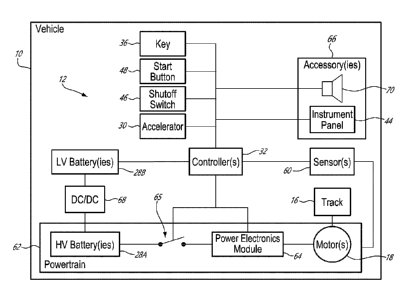
provided
on a display screen of instrument panel 44 for example.
[00173] In various embodiments, instrument panel 44 may include a
liquid crystal
display (LCD) screen, thin-film-transistor (TFT) LCD screen, light-emitting
diode (LED) or
other suitable display device operatively connected to controller 32. In some
embodiments, instrument panel 44 may be touch-sensitive to facilitate operator
inputs. In
some embodiments, instrument panel 44 may be capable of producing images in
color or
monochrome. Instrument panel 44 may be capable of displaying a speedometer and
other instrumentation in the form of one or more digital readouts and/or
analog gauges.
As explained further below, instrument panel 44 may be capable of being
controlled by
controller 32 to provide an illumination of the instrumentation and/or other
information
using different illumination colors that may be selected according to the
state of vehicle
10. The use of different illumination colors may promote enhanced operator
awareness
of the state of vehicle 10 during the activation and operation of vehicle 10
for example.
[00174] Operator interface 42 of vehicle 10 may include (e.g.,
emergency) shutoff
switch 46, sometimes referred to as a "kill switch", operatively connected to
controller 32.
Shutoff switch 46 may be disposed on or close to handlebar 24 or at another
suitable
location that is readily accessible by the operator when the operator is in
the normal
driving position. The actuation of shutoff switch 46 by the operator may also
provide the
-27 -
Date Recue/Date Received 2022-04-07
capability of automatically stopping propulsion of vehicle 10 when vehicle 10
is in motion
to prevent vehicle runaway when an emergency situation is perceived by the
operator.
[00175] Operator interface 42 of vehicle 10 may include start button
48 (e.g., a
physical push button) or other input device(s) (e.g., rotary switch(es),
multiple push
buttons, receptacle 38 and key 36) suitable for activating vehicle 10. In
embodiments
using start button 48, successive pressing/actuations of start button 48 may
successively
change the state of vehicle 10 as explained below. Start button 48 may be
disposed on
or close to handlebar 24 or at another suitable location that is readily
accessible by the
operator. In some embodiments, start button 48 may be disposed at a location
other than
on handlebar 24 such as on a body panel or on instrument panel 44 of vehicle
10 for
example. Start button 48 may be disposed behind or forward of handlebar 24 for
example.
In embodiments using a rotary switch (and optionally a key) to activate
vehicle 10, such
rotary switch may include different angular positions corresponding to the
different states
of vehicle 10 described herein.
[00176] FIG. 2 shows an exemplary representation of key 36 and of start
button
48 associated with vehicle 10. During operation of vehicle 10, key 36 may be
tethered to
the operator via tether 40. In some embodiments, key 36 may be part of a radio-
frequency
identification (RFID) system of vehicle 10. Key 36 may include RFID tag 52
which may
store data identifying key 36 or a specific operator associated with key 36.
When triggered
by an electromagnetic interrogation pulse from a RFID reader device associated
with
vehicle 10 and operatively connected to controller 32, RFID tag 52 may
wirelessly
transmit the data stored on RFID tag 52 and the data may be used by controller
32 to
authenticate key 36 and either permit or prevent the operation of vehicle 10
based on the
data. The use of key 36 as part of a RFID system of vehicle 10, the use of a
PED in
communication with controller 32, and/or the use of a code or password entered
by the
operator may allow controller 32 to implement a software-based tether switch
54, shown
schematically in FIG. 2, that may be used to signal the operator's
authorization to use
vehicle 10.
[00177] In some embodiments, tether switch 54 may be a
physical/mechanical
hardware-based switch that physically interacts with key 36. For example,
tether switch
54 may be disposed within receptacle 38 so that the insertion and withdrawal
of key 36
-28 -
Date Recue/Date Received 2022-04-07
into and out of receptacle 38 may cause key 36 to interface with and actuate
tether switch
54 and signal to controller 32 the operator's authorization to use vehicle 10
and/or the
presence or absence of the operator onboard vehicle 10.
[00178] Start button 48 may be disposed in proximity to receptacle
38. Start button
48 may be operatively connected to controller 32 via start switch 56. Start
switch 56 may
cause electrical power to be delivered to controller 32 to cause controller 32
to start up.
An initial press of start button 48 may cause controller 32 to start up and
one or more
subsequent presses of start button 48 may instruct controller 32 to transition
vehicle 10
to one or more different states. In some embodiments, an integrated circuit
powered by
LV battery 28B and exhibiting relatively low power consumption may be
operatively
connected to start button 48 and to controller 32 to detect actuations of
start button 48
and instruct controller 32 accordingly. Such integrated circuit may have the
form of a
system basis chip (SBC) that includes suitable embedded functions. Start
button 48 may
be green or of another color providing relatively high visibility and
distinguishing the
function of start button 48 from that of shutoff switch 46 or other input
device(s). Start
button 48 may be relatively easy to actuate while wearing gloves for example.
[00179] FIG. 3 shows an exemplary representation of shutoff switch 46
associated
with vehicle 10. Shutoff switch 46 may be mounted to handlebar 24 in proximity
to
accelerator 30 and hand grip 58 so that a (e.g., right) hand of the operator
used to actuate
accelerator 30 may also be used to actuate shutoff switch 46. Shutoff switch
46 may
include a physical push button, rotary knob or toggle switch that may actuated
between
two positions such as vehicle-ON and vehicle-OFF shown in the inset of FIG. 3.
Actuating
shutoff switch 46 from the vehicle-ON (e.g., up) position to the vehicle-OFF
(e.g., down)
position when vehicle 10 is in motion may be used to signal to controller 32
that propulsion
of vehicle 10 is to be stopped. Shutoff switch 46 may signal to controller 32
that propulsion
of vehicle 10 is to be prevented when shutoff switch 46 is in the vehicle-OFF
configuration.
Shutoff switch 46 may signal to controller 32 that propulsion of vehicle 10
may be
permitted when shutoff switch 46 is in the vehicle-ON configuration. Shutoff
switch 46
may be configured to remain in its ON or OFF positions without requiring
continuous
contact from the operator's hand. Shutoff switch 46 may be red, orange or
other color
providing relatively high visibility.
-29 -
Date Recue/Date Received 2022-04-07
[00180] FIG. 4 is a schematic representation of vehicle 10 including
vehicle
activation system 12. System 12 may include one or more sensors 60 operatively
connected to component(s) of powertrain 62 of electric vehicle 10 and also to
controller
32. Powertrain 62 may include one or more high-voltage (HV) batteries 28A
(referred
hereinafter in the singular), power electronics module 64 and motor 18.
Sensor(s) 60 may
be configured to sense one or more operating parameters of powertrain 62 for
use by
controller 32 for regulating the operation of motor 18 and/or controlling
other aspects of
vehicle 10. HV battery 28A may be electrically connected or electrically
disconnected
from PEM 64 using one or more switches 65 (e.g., contactor(s)) controllable
via controller
32. Key 36, start button 48, shutoff switch 46 and accelerator 30 may be
operatively
connected to controller 32.
[00181] The operation of motor 18 and the delivery of electric power
to motor 18
may be controlled by controller 32 via a suitable power electronics module 64
(referred
hereinafter as "PEM 64") including electronic switches (e.g., insulated gate
bipolar
transistor(s)) to provide motor 18 with electric power having the desired
voltage, current,
waveform, etc. to implement the desired performance of vehicle 10 based on an
actuation
of accelerator 30 by the operator indicating a command to propel vehicle 10.
PEM 64 may
include an assembly containing power components such as power semiconductor
devices interconnected to perform a power conversion function. In some
embodiments,
power electronics module 64 may include a power inverter for example. HV
battery 28A
may include a lithium ion or other type of battery. In some embodiments, HV
battery 28A
may be configured to output electric power at a voltage of about 300 volts.
[00182] Sensor(s) 60 may include one or more current sensors and/or
one or more
voltage sensors operatively connected to HV battery 28A and/or connected to
PEM 64.
Sensor(s) 60 may include one or more position sensors (e.g., rotary encoder)
and/or
speed sensors (e.g., tachometer) suitable for measuring the angular position
and/or
angular speed of a rotor of motor 18 and/or of another rotating component of
powertrain
62. Sensor(s) 60 may include one or more torque sensors (e.g., a rotary torque
transducer) for measuring an output torque of motor 18. Alternatively, the
output torque
of motor 18 may be inferred based on the amount of electric power (e.g.,
current) being
supplied to motor 18 for example.
- 30 -
Date Recue/Date Received 2022-04-07
[00183] Controller 32, may be configured to, using PEM 64 and
sensor(s) 60,
control motor 18 to propel vehicle 10 based on commands received via
accelerator 30.
Controller 32 may also be configured to control motor 18 during (e.g.,
regenerative)
braking when motor 18 is back-driven due to motion of vehicle 10 and is
operated as a
generator. During regenerative braking, electrical power generated by motor 18
may be
returned to the supply line for charging HV battery 28A.
[00184] Vehicle 10 may include one or more low-voltage (LV) batteries
28B
(referred hereinafter in the singular) to supply electric power to controller
32 and optionally
other low-voltage devices such as accessories 66. In some embodiments, LV
battery 28B
may include one or more lead-acid batteries. In some embodiments, LV battery
28B may
be configured to output electric power at a voltage of about 12 volts. LV
battery 28B may
electrically connectable to controller 32 either directly or via a suitable
DC/DC converter
68. Low-voltage accessories 66 may include speaker 70 and instrument panel 44
for
example. LV battery 28B may be chargeable using electric power from HV battery
28A at
a voltage that is reduced using DC/DC converter 68.
[00185] FIG. 5 is a schematic representation of controller 32 of
vehicle activation
system 12. Controller 32 may include one or more data processors 72 (referred
hereinafter as "processor 72") and non-transitory machine-readable memory 74.
Controller 32 may be configured to regulate the operation of motor 18 via PEM
64, and
optionally also control other aspects of operation of vehicle 10. Controller
32 may receive
input(s) 76, perform one or more procedures or steps defined by instructions
78 stored in
memory 74 and executable by processor 72 to generate output(s) 80. Controller
32 may
include multiple controllers including a vehicle controller, a battery
controller (e.g., battery
management system), and a motor controller for example.
[00186] Controller 32 may carry out additional functions than those
described
herein. Processor 72 may include any suitable device(s) configured to cause a
series of
steps to be performed by controller 32 so as to implement a computer-
implemented
process such that instructions 78, when executed by controller 32 or other
programmable
apparatus, may cause the functions/acts specified in the methods described
herein to be
executed. Processor 72 may include, for example, any type of general-purpose
microprocessor or microcontroller, a digital signal processing (DSP)
processor, an
- 31 -
Date Recue/Date Received 2022-04-07
integrated circuit, a field programmable gate array (FPGA), a reconfigurable
processor,
other suitably programmed or programmable logic circuits, or any combination
thereof.
[00187] Memory 74 may include any suitable machine-readable storage
medium.
Memory 74 may include non-transitory computer readable storage medium such as,
for
example, but not limited to, an electronic, magnetic, optical,
electromagnetic, infrared, or
semiconductor system, apparatus, or device, or any suitable combination of the
foregoing. Memory 74 may include a suitable combination of any type of machine-
readable memory that is located either internally or externally to controller
32. Memory
74 may include any storage means (e.g. devices) suitable for retrievably
storing machine-
readable instructions 78 executable by processor 72.
[00188] Various aspects of the present disclosure may be embodied as
systems,
devices, methods and/or computer program products. Accordingly, aspects of the
present
disclosure may take the form of an entirely hardware embodiment, an entirely
software
embodiment or an embodiment combining software and hardware aspects.
Furthermore,
aspects of the present disclosure may take the form of a computer program
product
embodied in one or more non-transitory computer readable medium(ia) (e.g.,
memory
74) having computer readable program code (e.g., instructions 78) embodied
thereon.
Computer program code for carrying out operations for aspects of the present
disclosure
in accordance with instructions 78 may be written in any combination of one or
more
programming languages. Such program code may be executed entirely or in part
by
controller 32 or other data processing device(s). It is understood that, based
on the
present disclosure, one skilled in the relevant arts could readily write
computer program
code for implementing the methods described and illustrated herein.
[00189] FIG. 6 shows a flow diagram of an exemplary method 100 of
activating
vehicle 10, or another electric (e.g., powersport) vehicle. Machine-readable
instructions
78 may be configured to cause controller 32 to perform at least part of method
100.
Aspects of method 100 may be combined with other actions or aspects of other
methods
described herein. Aspects of vehicles described herein may also be
incorporated into
method 100.
[00190] The activation or start-up of vehicle 10 may include transitioning
vehicle
10 from an inactive (i.e., OFF) state to an intermediate partially active
(i.e., WAKE) state,
- 32 -
Date Recue/Date Received 2022-04-07
and then to a fully active (i.e., READY) state. Method 100 may make use of a
two-input-
command approach for transitioning vehicle 10 from the inactive state to the
ready state
where vehicle 10 may be propelled. In various embodiments, the two commands
may be
received via a common operator input device such as start button 48.
Alternatively, the
two commands may be received via different operator input devices.
[00191] In various embodiments, method 100 may include:
when vehicle 10 is in the OFF state (block 102), a first command to activate
vehicle 10 may be received (block 104);
in response to the first command, vehicle 10 may be transitioned from the
OFF state to the WAKE state (block 106);
after receiving the first command, a second command to activate vehicle
10 may be received (block 108); and
in response to the second command, vehicle 10 may be transitioned from
the WAKE state to the READY state (block 110).
[00192] In some embodiments, method 100 may optionally include, after
receiving
the second command, receiving a third command to activate vehicle 10 (block
112). In
response to the third command, vehicle 10 may be transitioned from the READY
state to
the WAKE state at block 106. The operator of vehicle 10 may send the third
command
during a brief pause after having driven vehicle 10.
[00193] In the OFF sate, vehicle 10 may be in a partially or fully inactive
state
where some or all of controller(s) 32, accessories 66 and instrument panel 44
may be off.
In some embodiments, electric power may not be supplied to controller 32, to
accessories
66 and/or to instrument panel 44 when vehicle 10 is in the OFF state.
Similarly, switch 65
may be open so that HV battery 28A is electrically disconnected from PEM 64 so
that
vehicle 10 may not be propelled via motor 18 when vehicle 10 is in the OFF
state. Vehicle
10 may be placed in the OFF state in preparation for a period of inactivity of
vehicle 10
and/or when vehicle 10 is to be left unattended for example.
[00194] The receipt of the first command (e.g., via start button 48)
at block 104
may, for example, establish an electric connection between LV battery 28B and
controller
32 so that controller 32 may be powered-up and activated. Once controller 32
has been
- 33 -
Date Recue/Date Received 2022-04-07
activated, controller 32 may be responsive to subsequent actuations of start
button 48 in
order to transition vehicle 10 to the desired state.
[00195] During the WAKE state, one or more preparatory tasks may be
carried out
in preparation for the driving of vehicle 10 but propulsion of vehicle 10 via
motor 18 may
be prevented. In other words, propulsion commands received via accelerator 30
(i.e.,
accelerator commands) may be ignored by controller 32 when vehicle 10 is in
the WAKE
state. As explained below, a visual or other type of indication may be
provided to the
operator (e.g., via instrument panel 44) to indicate the WAKE state of vehicle
10. In the
WAKE state, some operator interaction with vehicle 10 may be permitted via
operator
interface 42. For example, an operator may interact with operator interface 42
to select
an operation mode (e.g., eco, normal, sport) for vehicle 10 or adjust other
vehicle settings.
[00196] The receipt of the second command, as a subsequent actuation
of start
button 48 for example, may cause vehicle 10 to transition from the WAKE state
to the
READY state where vehicle 10 may be driven. In the READY state, propulsion of
vehicle
10 via motor 18 may be permitted and propulsion commands received via
accelerator 30
(i.e., accelerator commands) may be executed by controller 32. As explained
below, a
visual or other type of indication may be provided to the operator (e.g., via
instrument
panel 44) to indicate the READY state of vehicle 10.
[00197] In some embodiments of method 100, the transition of vehicle
10 from the
OFF state to the WAKE state may not require an operator's authorization to
operate
vehicle 10 being received via key 36 or otherwise. However, in some
embodiments of
method 100, the transition of vehicle 10 from the OFF state to the WAKE state
may be
conditioned upon the operator's authorization to operate vehicle 10 having
been received.
Similarly, in some embodiments of method 100, the transition of vehicle 10
from the
WAKE state to the READY state may be conditioned upon the operator's
authorization to
operate vehicle 10 having been received. Still further, in some embodiments of
method
100, the transition of vehicle 10 from the WAKE state to the READY state may
be
conditioned upon shutoff switch 46 being in a vehicle-ON (e.g., up) position.
Still further,
in some embodiments of method 100, the transition of vehicle 10 from the WAKE
state
to the READY state may be conditioned upon the accelerator 30 being in an un-
activated
position (e.g. such that is does not issue an accelerator command).
- 34 -
Date Recue/Date Received 2022-04-07
[00198] In some embodiments of method 100 and other methods described
herein,
the transition of vehicle 10 from the WAKE state to the OFF state may occur
automatically
if vehicle 10 is left in either the WAKE state or the READY state without
interaction for a
time period that exceeds a prescribed threshold for example. In some
embodiments,
vehicle 10 may be transitioned to the OFF state manually by a relatively
longer (e.g., a
few seconds) press of start button 48 for example. In other words, vehicle 10
may be
transitioned to the OFF state manually by pressing of start button 48 for a
period of time
that exceeds a prescribed threshold.
[00199] FIG. 7 shows a flow diagram of another exemplary method 200
of
activating vehicle 10, or another electric (e.g., powersport) vehicle. Machine-
readable
instructions 78 may be configured to cause controller 32 to perform at least
part of method
200. Aspects of method 200 may be combined with other actions or aspects of
other
methods described herein. Aspects of vehicles described herein may also be
incorporated into method 200. In various embodiments, method 200 may include:
when vehicle 10 is in the OFF state (block 202), a first command to activate
vehicle 10 may be received via an operator input device disposed on vehicle 10
(block
204);
in response to the first command, vehicle 10 may be transitioned from the
OFF state to the WAKE state where controller 32 of vehicle 10 is activated and
vehicle
10 is prevented from being propelled by motor 18 (block 206);
after receiving the first command, a second command to activate vehicle
10 may be received via the operator input device (block 208) when shutoff
switch 46 is in
the vehicle-on configuration (block 210); and
in response to the second command, vehicle 10 may be transitioned from
the WAKE state to the READY state where vehicle 10 is permitted to be
propelled by
motor 18 (block 212).
[00200] In some embodiments, the first and second commands may both
be
received via start button 48. In a situation where shutoff switch 46 would be
in the vehicle-
OFF configuration when the second command is received, the transition of
vehicle 10 to
the READY state may not be permitted by controller 32. In such scenario
encountered at
- 35 -
Date Recue/Date Received 2022-04-07
decision block 210, no action may be taken or a suitable alert may be
generated at block
214 to alert the operator to put shutoff switch 46 in the vehicle-ON
configuration before
sending the second command by pressing start button 48 again for example. In
some
embodiments, such alert may include an audible indication (e.g., beep)
generated using
speaker 70 for example. Alternatively or in addition, the alert may include a
visual and/or
or a haptic indication provided for the operator.
[00201] In some embodiments of method 200, after receiving the second
command and when vehicle 10 is in the READY state, a third command may be
received
from the operator input device (e.g., as a subsequent actuation of start
button 48) at block
216. In response to the third command, vehicle 10 may be transitioned from the
READY
state to the WAKE state at block 206.
[00202] FIG. 8 shows a flow diagram of another exemplary method 300
of
activating vehicle 10, or another electric (e.g., powersport) vehicle. Machine-
readable
instructions 78 may be configured to cause controller 32 to perform at least
part of method
300. Aspects of method 300 may be combined with other actions or aspects of
other
methods described herein. Aspects of vehicles described herein may also be
incorporated into method 300. In various embodiments, method 300 may include:
when vehicle 10 is in the OFF state (block 302), a first command to activate
vehicle 10 may be received (block 304);
in response to the first command, vehicle 10 may be transitioned from the
OFF state to the WAKE state (block 306) where:
controller 32 may be activated;
vehicle 10 may be prevented from being propelled by motor 18; and
regenerative (or other form of) braking of motor 18 may be caused when
vehicle 10 is in motion causing back-driving of motor 18;
after receiving the first command, a second command to activate vehicle
10 may be received (block 308); and
- 36 -
Date Recue/Date Received 2022-04-07
in response to the second command, vehicle 10 may be transitioned from
the WAKE state to the READY state where vehicle 10 may be permitted to be
propelled
by motor 18 (block 310).
[00203] In some embodiments, the first and second commands may both
be
received via start button 48.
[00204] In the WAKE state, a regenerative braking function of vehicle
10 may be
enabled (armed) so as to be ready to be used if needed. For example, in the
event where
vehicle 10 is parked on a hill while in the WAKE state, motion of vehicle 10
down the hill
due to gravity could potentially cause back-driving of motor 18 and hence
cause motor
18 to operate as a generator. Controller 32 may then cause regenerative or
other form of
braking of motor 18. Such regenerative braking may then cause a load (torque)
to be
applied to motor 18 and provide some resistance hindering the movement of
vehicle 10.
Such regenerative braking may, in some situations, prevent vehicle 10 from
unintentionally speeding down the hill in case of friction brake 34 not being
engaged when
vehicle 10 is parked for example.
[00205] In some embodiments of method 300, after receiving the second
command and when vehicle 10 is in the READY state, a third command may be
received
from the operator input device (e.g., as a subsequent actuation/press of start
button 48)
at block 312. In response to the third command, vehicle 10 may be transitioned
from the
READY state to the WAKE state at block 306.
[00206] FIG. 9 shows a flow diagram of another exemplary method 400
of
activating vehicle 10, or another electric (e.g., powersport) vehicle. Machine-
readable
instructions 78 may be configured to cause controller 32 to perform at least
part of method
400. Aspects of method 400 may be combined with other actions or aspects of
other
methods described herein. Aspects of vehicles described herein may also be
incorporated into method 400. Method 400 is described in reference to FIGS.
10A and
10B. In various embodiments, method 400 may include:
when vehicle 10 is in the OFF state (block 402), a first command to activate
vehicle 10 may be received via an operator input device disposed on vehicle 10
(block
404);
- 37 -
Date Recue/Date Received 2022-04-07
in response to the first command, vehicle 10 may be transitioned from the
OFF inactive state to the WAKE state (block 406) where:
controller 32 of vehicle 10 may be activated;
capacitor 82 (shown in FIGS. 10A and 10B) of PEM 64 operatively
disposed between HV battery 28A and motor 18 may be charged; and
vehicle 10 may be prevented from being propelled by motor 18;
after receiving the first command, a second command to activate vehicle
may be received via the operator input device (block 408); and
in response to the second command, vehicle 10 may be transitioned from
10 the WAKE state to the READY state where vehicle 10 may be permitted to
be propelled
by motor 18 (block 410).
[00207] In some embodiments, the first and second commands may both
be
received via start button 48.
[00208] FIGS. 10A and 10B show different configurations of an
exemplary circuit
83 for activating vehicle 10. PEM 64 may be operatively connected between HV
battery
28A and motor 18 to control the delivery of electric power from HV battery 28A
to motor
18. Motor 18 may be a polyphase (e.g., 3-phase) synchronous motor and may
include a
plurality of armature (e.g., stator) windings such as armature windings L1,
L2, L3.
Armature windings Ll, L2, L3 may be connected in a wye or delta configuration.
Neutral
point N may be connected to ground G.
[00209] PEM 64 may include inverter 84 and capacitor 82 may be
electrically
connected in parallel with inverter 84. Capacitor 82 may be a smoothing
capacitor within
PEM 64. Circuit 83 may also include fuse 86 operative to provide overcurrent
protection
for circuit 83.
[00210] The electric connection of HV battery 28A to PEM 64 when vehicle 10
is
transitioned from the OFF state to the WAKE state may be done using a suitable
inrush
current limiting device such as positive temperature coefficient (PTC)
thermistor 88 for
example. The current limiting device may prevent excessive inrush current from
HV
- 38 -
Date Recue/Date Received 2022-04-07
battery 28A when HV battery 28A is electrically connected to PEM 64 and
capacitor 82
is charged.
[00211] When transitioning vehicle 10 from the OFF state to the WAKE
state, HV
battery 28A may be initially connected to PEM 64 by closing of switches 65A
and 65B as
shown in FIG. 10A. Such connection may connect PTC thermistor 88 in series
with PEM
64 and with capacitor 82 and thereby limit inrush current from HV battery 28A
as capacitor
82 is charged. In some embodiments, the charging of capacitor 82 may take
about 1-2
seconds for example. After such time period, switch 65C may be closed as shown
in FIG.
10B to provide an electric connection to PEM 64 that bypasses PTC thermistor
88 in
preparation for propulsion of vehicle 10 via PEM 64.
[00212] In preparation for propulsion of vehicle 10, switch 65A may
be opened
while switches 65B and 65C are closed. Switches 65A-65C may be operatively
connected
to be controlled via controller 32. Components of circuit 83 such as PTC
thermistor 88
and one or more of switches 65A-65C may be disposed on a circuit board that is
part of
the battery management system (BMS) of vehicle 10. In some embodiments, switch
65A
may be disposed on a circuit board that is part of the battery management
system (BMS)
and switches 65B, 65C may be high power relays mounted to a frame or structure
of a
battery pack.
[00213] The configuration of circuit 83 shown in FIG. 10B may be
adopted in the
WAKE state of vehicle 10 in preparation for the transition to the READY state.
In other
words, the transition from the OFF state to the WAKE state may cause switches
65B and
65C to be closed so that HV battery 28A may be electrically connected to
inverter 84 of
PEM 64. Even though HV battery 28A may be electrically connected to PEM 64,
the
propulsion of vehicle 10 may be prevented by preventing electric power from
being
delivered to motor 18 via inverter 84. Preventing propulsion of vehicle 10
while in the
WAKE stage may be done by controller 32 not executing (e.g., ignoring)
propulsion
commands that may be received via accelerator 30 when vehicle 10 is in the
WAKE state.
Ignoring propulsion commands may include controller 32 keeping the switches of
inverter
84 in a configuration where electric power is not supplied to motor 18. In
other words,
while in the WAKE state, controller 32 may be programmed not to control
inverter 84
according to propulsion commands that may be received via accelerator 30.
- 39 -
Date Recue/Date Received 2022-04-07
[00214] In reference to FIG. 9 again, in some embodiments of method
400, after
receiving the second command and when vehicle 10 is in the READY state, a
third
command may be received from the operator input device (e.g., as a subsequent
actuation of start button 48) at block 412. In response to the third command,
vehicle 10
may be transitioned from the READY state to the WAKE state at block 406.
[00215] In some embodiments, repeated transitioning between the WAKE
state
and the READY state by pressing start button 48 for example may cause HV
battery 28A
to remain electrically connected to PEM 64 and capacitor 82 to remain charged.
Accordingly, the configuration of circuit 83 shown in FIG 10B may be retained
during
transitions between the WAKE and READY states. This may avoid repeated opening
and
closing of switches 65A-65B during such transitions and may consequently
suppress the
degradation of switches 65A-65B due to frequent switching.
[00216] FIG. 11 shows a flow diagram of another exemplary method 500
of
activating vehicle 10, or another electric (e.g., powersport) vehicle. Machine-
readable
instructions 78 may be configured to cause controller 32 to perform at least
part of method
500. Aspects of method 500 may be combined with other actions or aspects of
other
methods described herein. Aspects of vehicles described herein may also be
incorporated into method 500. Method 500 is described in reference to FIGS.
12A-12C.
In various embodiments, method 500 may include:
when vehicle 10 is in the OFF state (block 502), a first command to activate
vehicle 10 may be received (block 504);
in response to the first command, vehicle 10 may be transitioned from the
OFF state to the WAKE state (block 506) where:
controller 32 of vehicle 10 is activated;
vehicle 10 is prevented from being propelled by motor 18; and
first visual indication 90A (e.g. of a first color, texture or pattern) may be
provided to indicate the WAKE state of vehicle 10;
after receiving the first command, a second command to activate vehicle
10 may be received (block 508); and
- 40 -
Date Recue/Date Received 2022-04-07
in response to the second command, vehicle 10 may be transitioned from
the WAKE state to the READY state (block 510) where:
vehicle 10 is permitted to be propelled by motor 18; and
second visual indication 90B (e.g. of a second color, texture or pattern)
different from the first color, texture or pattern may be provided to indicate
the READY
state of vehicle 10.
[00217] In some embodiments, the first and second commands may both
be
received via start button 48.
[00218] FIGS. 12A-12C show exemplary graphic representations
displayed on
instrument panel 44 of vehicle 10. Visual indications 90A-90C may be provided
on
instrument panel 44 and/or at another location on vehicle 10 that is readily
visible by
operator so as to promote the operator's awareness of the state of vehicle 10.
In some
embodiments, visual indications 90A-90C may be provided by a single variable-
color
indicator light (e.g., variable color LED), or by multiple indicator lights of
different colors
for example. In some embodiments, visual indications 90A-90C may include one
or more
textual and/or graphic indications indicative of the state of vehicle 10 for
example. In some
embodiments as shown in FIGS. 12A-12C, visual indications 90A-90C may be
provided
by way of different background and/or foreground illumination colors of
instrument panel
44.
[00219] FIG. 12A shows an exemplary graphic representation displayed on
instrument panel 44 of vehicle 10 when vehicle 10 is in the WAKE state and in
a neutral
mode of operation as indicated by the letter "N" being circled at the bottom
of instrument
panel 44. When vehicle 10 is transitioned from the OFF state to the WAKE
state,
instrument panel 44 may be transitioned from being unlit to being lit, with at
least some
of the instrument panel 44 being shown in a first illumination color (e.g.,
gray) that is
indicative of the WAKE state. In the example of FIG. 12A, some or all of the
textual and/or
graphic indications or a background of instrument panel 44 may be shown in the
first
illumination color to provide first visual indication 90A.
[00220] FIG. 12B shows an exemplary graphic representation displayed
on
instrument panel 44 of vehicle 10 when vehicle 10 is in the READY state and in
a forward
- 41 -
Date Recue/Date Received 2022-04-07
(drive) mode of operation as indicated by the letter "D" being circled at the
bottom of
instrument panel 44. When vehicle 10 is transitioned from the WAKE state to
the READY
state, at least some of the instrument panel 44 may be transitioned from
having the first
illumination color (e.g., gray) indicative of the WAKE state to having the
second
illumination color (e.g., green) indicative of the READY state. In the example
of FIG. 12B,
some or all of the textual and/or graphic indications or the background may be
shown in
the second illumination color to provide second visual indication 90B.
[00221] In reference to FIG. 11 again, in some embodiments of method
500, after
receiving the second command and when vehicle 10 is in the READY state, a
third
command may be received from the operator input device (e.g., as a subsequent
actuation of start button 48) at block 512. In response to the third command,
vehicle 10
may be transitioned from the READY state to the WAKE state at block 506.
[00222] In some embodiments, repeated transitioning (i.e., toggling)
between the
WAKE state and the READY state by pressing start button 48 for example may
cause
corresponding transitioning between the first and second visual indications
90A, 90B
being provided in order to reflect the corresponding WAKE or READY states of
vehicle
10. In the example shown in FIGS. 12A and 12B, transitioning between the WAKE
and
READY states may cause the illumination color of instrument panel 44 to be
changed
accordingly.
[00223] FIG. 12C shows an exemplary graphic representation displayed on
instrument panel 44 of vehicle 10 when vehicle 10 is in the READY state and in
a reverse
mode of operation as indicated by the letter "R" being circled at the bottom
of instrument
panel 44. When vehicle 10 is in the READY state and transitioned between the
forward
and reverse modes of operation, second visual indication 90B indicative of the
READY
state may be changed accordingly. FIG. 12C shows third visual indication 90C
indicative
of vehicle 10 being in the READY state and reverse mode of operation to
promote the
operator's awareness of the state of vehicle 10. When vehicle 10 is
transitioned from the
forward mode of operation to the reverse mode of operation, instrument panel
44 may be
transitioned from displaying the second illumination color (e.g., green)
indicative of the
forward mode of operation to displaying a third illumination color (e.g.,
orange) indicative
of the reverse mode of operation. In the example of FIG. 12C, some or all of
the textual
-42 -
Date Recue/Date Received 2022-04-07
and/or graphic indications and/or the background may be shown in the third
illumination
color to provide third visual indication 90C.
[00224] The embodiments described in this document provide non-
limiting
examples of possible implementations of the present technology. Upon review of
the
present disclosure, a person of ordinary skill in the art will recognize that
changes may
be made to the embodiments described herein without departing from the scope
of the
present technology. Further modifications could be implemented by a person of
ordinary
skill in the art in view of the present disclosure, which modifications would
be within the
scope of the present technology.
- 43 -
Date Recue/Date Received 2022-04-07