Note: Descriptions are shown in the official language in which they were submitted.
DRUM AND DOOR ASSEMBLY FOR CATALYTIC MICROWAVE
DEPOLYMERIZATION REACTOR
[0001] BACKGROUND
(a) Field
[0002] The subject matter disclosed generally relates to elements of
microwave reactors. More specifically, the subject matter relates to door
assemblies, drums and their use in microwave depolymerization reactors.
(b) Related Prior Art
[0003] Microwave depolymerization uses an electromagnetic field that
interacts with microwave absorbing material (the catalyst) to convert the
electrical
energy into heat. The electromagnetic field must be properly contained inside
the
reactor in order to ensure safety around the equipment when operated. Although
door chokes exist to contain microwave energy, no such choke technology exists
to choke the rather high power microwave radiations used in a rotating cavity
operating in a high temperature environment under thermal cycling.
[0004] During the depolymerization process, heat is transferred from
the
catalyst material to the material being depolymerized by conduction.
Therefore, a
key requirement during this process is being able to intimately contact the
catalyst
material with the polymer material being depolymerized by avoiding segregation
under mixing conditions. Typical approaches for avoiding segregation rely on
the
use of baffles to promote mixing. However, the use of baffles becomes rather
difficult when a high energy electromagnetic field is present in the mixing
cavity
because it triggers electrical arcs that decrease the performance of the
depolymerization process. Therefore, there is a need for technology to ensure
1
Date Recue/Date Received 2022-08-05
proper mixing in a rotating drum while avoiding the presence of protrusions
and
sharp edges that will trigger electrical arcs. In addition, there is a need
for
technology that would allow the operation at high temperature in the presence
of
high power microwave radiations.
[0005] During microwave depolymerization, the presence of sharp
edges
and protruding elements can result in electric arcing and consequent damage to
the reactor. In order to avoid this, sharp edges and protrusions have to be
avoided,
either by not including them in the initial design, or by polishing any
problematic
elements (e.g. edges, welds, etc.) prior to use of the reactor. The need to
avoid
sharp edges and protrusions may be problematic with mixing of the material
being
treated. In some other applications in absence of microwave radiations, mixing
can
be enhanced in a rotating drum by adding flat sections around that would
generate
discontinuities in the flow and promote mixing. However, when subject to
thermal
cycling and in presence of high energy electrical field, those flat surfaces
are
subject to thermal deformation which, under cycling, will generate mechanical
fatigue inside the material and initiate cracks that would trigger arcs under
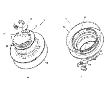
microwave radiations.
[0006] Therefore, there is a need for high temperature pyrolysis
microwave
reactors having alternate modes of mixing the material being treated therein.
[0007] Furthermore, under any circumstances, the process temperature
drops below melting point of the liquid present in the cavity due to loss of
microwave power during normal operation of the reactor, the liquid content
will
solidify. As a result, sharp edges will be formed at the surface of the
solidified
material and it will become impossible to reheat the content of the reactor
using
microwave energy as it will trigger arcs initiated by the sharp edges.
[0008] Therefore, there is a need in a catalytic microwave pyrolysis
depolymerization reactor for an alternate mean of heating the reactor to
maintain
reactor temperature above the melting point of the polymer liquid and above
the
2
Date Recue/Date Received 2022-08-05
dew point of the gas inside the reactor to avoid formation of sharp edges and
avoid
thermal shocks on the coupler's interface material.
SUMMARY
[0009] According to an embodiment, there is provided door assembly
for a
microwave reactor comprising:
- a microwave waveguide to direct microwave from an external microwave
source to inside the microwave reactor, having a waveguide interface
for preventing backflow of a process gas into the waveguide;
- an inlet for entry of matter to be treated in the microwave reactor;
- a first seal at the periphery of the door assembly, to sealably interface
with a static front of the microwave reactor;
- a second seal, inserted into a groove on an inside face of the door
assembly, to sealably interface with an opening of a microwave reactor
drum, the groove having a width of about 12.9 inches (32.766 cm)
divided by an integer, the second seal to prevent solids and liquids from
flowing outside of said reactor drum;
- a ring choke, to contact a choke arranged on the periphery of the
opening of the reactor drum.
[0010] The door assembly may be further comprising an
instrumentation
port.
[0011] The waveguide interface may be configured to be at a
temperature
higher than the dew point of a gas inside the reactor.
[0012] The waveguide may comprise a heater.
[0013] The door assembly may further comprise a gutter to divert
flow of
liquid from said waveguide interface.
[0014] The contact of the ring choke with the choke may be
adjustable.
3
Date Recue/Date Received 2022-08-05
[0015] The groove on an inside face of the door assembly may be
configured to avoid electrical arcing.
[0016] The door assembly may be further comprising a heating
element.
[0017] The inlet has a diameter below the wavelength of the
microwave at
915 MHz.
[0018] The inlet has a diameter of 12.9 in or less (32.766 cm or
less).
[0019] The inlet has a diameter of 6 in or less (15.24 cm or less).
[0020] The groove may be on an annular surface of an insert
configured to
insert and seal an opening of the reactor drum.
[0021] The groove may be configured to avoid sharp edges,
protrusions and
combinations thereof.
[0022] The first and second seal may be made from a material having
a low
or high dielectric constant E'.
[0023] The first and second seal are made from a material having a
complex
permittivity E".
[0024] The material may be chosen from 99.5% purity alumina oxide,
99.8%
purity alumina oxide, silica oxide, graphite, and combinations thereof.
[0025] The ring choke may comprise means to increase the pressure to
modulate its position along the longitudinal axis of the reactor drum, to
increase
contact with the choke.
[0026] The means to increase the pressure may be a plurality of
knobs
located at the periphery of the ring choke.
[0027] The knobs may be sealed with a cap.
[0028] The ring choke may be made of brass.
4
Date Recue/Date Received 2022-08-05
[0029] According to another embodiment, there is provided a
microwave
choke comprising:
- a choke, having a front and a back, the back configured for being
attached to and contacting the periphery of an opening of a drum, and
the front having a groove having a width and a depth configured to
maximize impedance of the choke around at a frequency of about 915
MHz to about 2450 MHz;
- a finger ring, comprising a plurality of fingers to dissipate
electromagnetic energy from the microwave, the ring being attached to
the choke such that the fingers partly overlap the groove.
[0030] According to another embodiment, there is provided a
microwave
reactor drum comprising:
- a drum having an opening;
- a choke, having a front and a back, the back being attached to and
contacting the periphery of the opening, and the front having a groove
having a width and a depth configured to maximize impedance of the
choke around at a frequency of about 915 MHz to about 2450 MHz;
- a finger ring, comprising a plurality of fingers to dissipate
electromagnetic energy from the microwave, the ring being attached to
the choke such that the fingers partly overlap the groove.
[0031] The width and the depth are configured to maximize impedance
of
the choke around at a frequency of about 915 MHz.
[0032] The width may be about 2 11/16 1/8 inches (6.82625 0.3175 cm)
and the depth may be about 5/8 1/8 inches (1.5875 0.3175 cm).
[0033] The choke may be welded to the drum.
[0034] The ring fingers may be spaced about 11,25 inches (28.575 cm)
between each center.
Date Recue/Date Received 2022-08-05
[0035] The ring fingers may have a gap of about % inch (0.635 cm)
between
each ring fingers.
[0036] The ring fingers may have height of about 1.875 inches
(4.7625 cm).
[0037] The interior of the drum may be heated, to avoid
solidification of a
material therein.
[0038] The finger ring may be attached to the choke with thermally
expanding fastener.
[0039] The microwave choke or the microwave reactor drum may
comprise
an adjustement space to adjust said choke distance with said ring fingers for
thermal expansion to maintain a front gap between said ring fingers and said
static
wall.
[0040] The interior of the drum may be heated with electrical wires,
with
steam, or a combination thereof.
[0041] According to another embodiment, there is provided a high
temperature pyrolysis microwave reactor comprising:
- a reactor enclosure;
- a rotating drum, the rotating drum being horizontally mounted in the
enclosure, and having a frontal opening, the drum being eccentered by
about 2 to about 7 relative to the longitudinal axis of the drum;
- a microwave source emitting microwaves within the rotating drum.
[0042] The drum may be eccentered by about 4 .
[0043] The rotating drum may comprise an inner drum and an outer
drum.
[0044] The gap between said inner drum and said outer drum is
isolated.
[0045] The drum may be a microwave reactor drum according to the
present
invention.
6
Date Recue/Date Received 2022-08-05
[0046] The high temperature pyrolysis microwave reactor of the
present
invention may comprise a door assembly according to the present invention.
[0047] The high temperature pyrolysis microwave reactor of the
present
invention drum may comprise a microwave reactor drum according to the present
invention, and comprising a door assembly according to the present invention.
[0048] Features and advantages of the subject matter hereof will
become
more apparent in light of the following detailed description of selected
embodiments, as illustrated in the accompanying figures. As will be realized,
the
subject matter disclosed and claimed is capable of modifications in various
respects, all without departing from the scope of the claims. Accordingly, the
drawings and the description are to be regarded as illustrative in nature, and
not
as restrictive and the full scope of the subject matter is set forth in the
claims.
BRIEF DESCRIPTION OF THE DRAWINGS
[0049] Further features and advantages of the present disclosure
will
become apparent from the following detailed description, taken in combination
with
the appended drawings, in which:
[0050] Fig. 1A illustrates a perspective view of the front of a door
assembly
according to an embodiment of the present invention.
[0051] Fig. 1B illustrates a perspective view of the back of a door
assembly
according to an embodiment of the present invention.
[0052] Fig. 2A illustrates an expanded view of the front of a door
assembly
according to an embodiment of the present invention.
[0053] Fig. 2B illustrates an expanded view of the back of a door
assembly
according to an embodiment of the present invention.
[0054] Fig. 3A illustrates a front view of right side of a door
assembly
according to an embodiment of the present invention.
7
Date Recue/Date Received 2022-08-05
[0055] Fig. 3B illustrates a front view of right left of a door
assembly
according to an embodiment of the present invention.
[0056] Fig. 3C illustrates a section view of a door assembly
according to an
embodiment of the present invention, showing the groove 26 of the first seal.
[0057] Fig. 3D illustrates a section view of a door assembly
according to an
embodiment of the present invention, showing the insert on which the groove 26
of the first seal is illustrated.
[0058] Fig. 3E illustrates a top down view of a door assembly
according to
an embodiment of the present invention.
[0059] Fig. 4A illustrates a front view of a ring choke according to
an
embodiment of the present invention.
[0060] Fig. 4B illustrates a knob to modulate the pressure on the
ring choke
according to an embodiment of the present invention.
[0061] Fig. 4C illustrates a side view of a ring choke according to
an
embodiment of the present invention.
[0062] Fig. 5A illustrates a perspective view of high temperature
pyrolysis
microwave reactor according to an embodiment of the present invention.
[0063] Fig. 5B illustrates a side view of a high temperature
pyrolysis
microwave reactor according to an embodiment of the present invention.
[0064] Fig. 5C illustrates a front view of a high temperature
pyrolysis
microwave reactor according to an embodiment of the present invention.
[0065] Fig. 5D illustrates a side view of a choke for use in a high
temperature
pyrolysis microwave reactor according to an embodiment of the present
invention.
[0066] Fig. 6A illustrates a side view of finger ring for use in a
high
temperature pyrolysis microwave reactor according to an embodiment of the
present invention.
8
Date Recue/Date Received 2022-08-05
[0067] Fig. 6B illustrates a front view of finger ring for use in a
high
temperature pyrolysis microwave reactor according to an embodiment of the
present invention.
[0068] Fig. 6C illustrates the relationship between the various
parts in the
door assembly of the present invention and the drum of the present invention,
which may be used in a front view of a high temperature pyrolysis microwave
reactor according to an embodiment of the present invention.
[0069] Fig. 6D illustrates the attachment of the finger ring to the
choke,
according to an embodiment of the present invention.
[0070] Fig. 6E illustrates the attachment of the finger ring to the
choke,
according to another embodiment of the present invention.
[0071] Fig. 7A illustrates a front view of right side of a door
assembly
according to an embodiment of the present invention.
[0072] Fig. 7B illustrates a front view of right left of a door
assembly
according to an embodiment of the present invention.
[0073] Fig. 7C illustrates a section view of a door assembly
according to an
embodiment of the present invention, showing the groove 26 of the first seal
and
the gutter 38.
[0074] It will be noted that throughout the appended drawings, like
features
are identified by like reference numerals.
DETAILED DESCRIPTION
[0075] In embodiments there is disclosed a door assembly 10 for a
microwave reactor. Now referring to Figs. 1, 2 and 3, the door assembly 10
comprises a microwave waveguide 12, to direct microwave from an external
microwave source to inside the microwave reactor. The microwave waveguide 12
has a waveguide interface 14 for preventing backflow of a process gas into the
waveguide 12. In embodiments, the waveguide 12 may be a circular waveguide,
9
Date Recue/Date Received 2022-08-05
or it may be a rectangular waveguide. Also present is an inlet 16, for entry
of matter
to be treated in the microwave reactor, such as for example the raw material
such
as plastics, or other polymeric materials, for example polystyrene, and may
also
be used to introduce other materials, such as water for steam generation
inside
the reactor when in use. In embodiments, the inlet can have a diameter below
the
wavelength of the microwave at 915 MHz (<12.9 in or 32.766 cm). In another
embodiment, the inlet 16 will typically be below 6 inches in diameters (15.24
cm),
so as to avoid excessive microwave leakage outside of the inlet chute.
In embodiments, the surface temperature around the waveguide interface 14
should remain at a temperature higher than the dew point of the gas inside the
reactor. It is preferable to avoid condensation of vapors on the surrounding
surfaces in order to avoid the flow of condensed liquid onto the waveguide
interface 14 and create thermal shock problems which would yield in complete
rupture of the waveguide interface material. According to an embodiment, the
waveguide interface 14 may be configured to be at a temperature higher than
the
dew point of a gas inside the reactor, for example, the waveguide 12 may
comprise
a heater.
[0076] According to another embodiment, the rotation of the drum
with liquid
material under mixing may entrain liquid at the top of the door and that
liquid may
flow downward onto the reactor drum all the way across the waveguide interface
14. To prevent this flow of liquid on the waveguide interface 14 material and
prevent thermal shocks from damaging the surface material, a gutter 38 (See
Fig.
7) is added on the door to divert flow of liquid from the waveguide interface
14.
[0077] The door assembly 10 also comprises a first seal 18, located
at the
periphery of the door assembly 10, which sealably interfaces with the static
front
of the microwave reactor. The door assembly 10 also comprises a second seal 20
to prevent solids and liquids from flowing outside of the reactor drum, which
is
inserted into a groove 26 on the inside face 22 of the door assembly 10, to
sealably
interface with an opening of a microwave reactor drum (not shown). According
to
Date Recue/Date Received 2022-08-05
an embodiment, the groove 26 is shown, on the annular surface of an insert 32,
which is configured to insert and seal the opening of a reactor drum. The
groove
26 has a width of about 12.9 inches (32.766 cm) divided by an integer (e.g.
12.9/1,
12.9/2, 12.9/3, 12.9/4, 12.9/5, 12.9/6, 12.9/7, 12.9/8, 12.9/9, 12.9/10,
etc.). In
embodiments, the groove 26 on an inside face 22 of the door assembly is
configured to avoid electrical arcing. For example, in addition to the
specific width,
the groove is machined so as so avoid sharp edges and protrusions which may be
causing arching. In embodiments, the first and second seal will be made from a
material which has low or high dielectric constant E' and complex permittivity
E".
Suitable materials include but are not limited to 99.5% purity alumina oxide,
99.8%
purity alumina oxide, silica oxide. The material for the seal may also be a
semiconductor such as graphite.
[0078]
The door assembly 10 also comprises a ring choke 28. The ring
choke 28, when the reactor is in use, will contact a choke arranged on the
periphery
of the opening of the reactor drum. The ring choke 28 prevents leakage of
microwave from the inside of the reactor. Now referring to Fig. 4, in use, the
contact
between the ring choke 28 and the choke should be maintained at all times.
Therefore, according to an embodiment, the contact between the ring choke 28
and the choke may be adjustable in order to increase pressure between the two
parts, and ensure appropriate contact. According to an embodiment, means to
increase the pressure may be built into the ring choke 28 to modulate its
position
along the longitudinal axis of the reactor drum, such that contact is
increased with
the choke. According to an embodiment, as shown in Fig. 4, the adjustment may
be performed by use of a plurality of knobs 30 located at the periphery of the
ring
choke 28. Upon actuation of the knob (e.g. turning them in this case), the
position
of the ring choke 28 may be modulated, and hence the pressure on the choke
increased or decreased. In embodiments, the ring choke 28 may be made of brass
so that it may slide over stainless steel without galling. Referring to Fig.
1A, the
plurality of knobs 30 is illustrated as protruding from the exterior face 24
of the door
11
Date Recue/Date Received 2022-08-05
assembly 10; which knobs pass through the exterior face 24 to attach to the
corresponding apertures (Fig. 4A). According to an embodiment, the knobs 30
may
be sealed with a cap.
[0079] According to another embodiment, the door assembly 10 may
also
comprise an instrumentation port 34, 34', to insert instruments to measure,
for
example the temperature, the oxygen content, and/or the pressure inside the
reactor, inside the reactor, the angular position of the reactor drum 100, the
distance between the choke elements, etc.
[0080] According to another embodiment, the door assembly 10 may
also
comprise a heating element 36 (See Fig. 1A), which is configured to maintain
the
temperature of the door assembly sufficiently high in order to prevent
condensation
and/or to avoid solidification of a material treated in the reactor thereon.
[0081] Now referring to Figs. 5 ¨ 6, in another embodiment there is
disclosed a microwave reactor drum 100. The microwave reactor drum 100
comprises a drum having an opening 102, and a choke 104, having a front 106
and a back 103, the back 103 being attached to and contacting the periphery of
the opening 102, and the front having a groove 110 having a width and a depth
configured to maximize impedance of the choke around at a frequency of about
915 to 2450 MHz, for example of about 2 11/16 1/8 inches (6.82625 0.3175 cm)
and a depth of about 5/8 1/8 inches (1.5875 0.3175 cm), which is selected to
maximize impedance around a frequency of 915 MHz so that the microwave
energy that leaks out of the reactor is curtailed. The specific dimensions of
the
groove 110 allow the choke 104 to curl the electrical field present when the
microwave reactor is in use, and contains the electromagnetic radiations
inside the
reactor. In an embodiment, the choke 104 is welded to the drum 100.
[0082] The choke 104 with the finger ring 112 is generally designed
to have
a maximum impedance around a frequency of 915 MHz so that the microwave
energy that leaks out of the gap 118 is less than 1 mV.
12
Date Recue/Date Received 2022-08-05
[0083] The microwave choke 104 is attached to a finger ring 112,
comprising a plurality of fingers 114 to dissipate electromagnetic energy from
the
microwave (Fig. 6). The finger ring 112 is attached to the choke 104 such that
the
fingers 114 partly overlap the groove 110 (Fig. 6C). The role of the choke
finger
ring 112 is to create the boundary between gap 118 and groove 110 in the choke
104. The appropriate gap 118 transforms high impedance at gap 130 to low
impedance, the spacing between the fingers 114 is designed as such because
when the microwave power is on there will be a high level of surface current
flowing. Too small of a space between the fingers 114 and the current will
jump
the gap and create an arc, too large of a space and its purpose of a boundary
is
null. If there are no gaps in the ring fingers 114 the ring will over heat.
According
to an embodiment, the ring fingers 114 are spaced by about 11,25 inches
(28.575
cm) between each center, with a gap of about 1/4 inch (0.635 cm), and a height
of
about 1.875 inches (4.7625 cm).
[0084] According to an embodiment, the finger ring 112 may be bolted
to
the choke 104. According to another embodiment, the finger ring 112 is
attached
to the choke 104 with thermally expanding fasteners, such as illustrated in
Fig. 6D,
which shows the finger ring 112 and finger 114 bolted to the choke 104, and a
space 116 is present to allow adjustment by adding variable thickness shims
for
thermal expansion in order to maintain the front gap 118 between the choke
fingers
114 and the static wall 120 within tolerances of 1/16" (0.15875 cm). Some
adjustment (space 116) is required to adjust the choke 104 distance with
maximum
tolerances of 1/16" (0.15875 cm). The width of gap 118 between the choke
fingers
114 and static wall 120 is about 3/16 1/8 of an inch (0.47625 0.3175 cm).
[0085] The ring choke 28 is there to ensure that the gap 130 (Fig.
6D) in the
choke 104 stays as small as possible especially during the expected expansion
of
the applicator as it heats.
[0086] According to another embodiment, the microwave reactor drum
100
may comprise means to heat the interior of the drum (i.e. the inner drum) to
avoid
13
Date Recue/Date Received 2022-08-05
solidification of a material therein after a microwave pyrolysis reaction, or
to liquefy
a material after it as solidified. According to an embodiment, the inner drum
is
heated with electrical wires to maintain the inner wall at a certain
temperature (for
example 200 C, or a minimum of 200 C, or higher, or lower, depending on the
material treated in the reactor) and avoid solidification of melted plastic or
wax
material at any given time. According to another embodiment, steam could be
used
to heat the inner drum.
[0087] During microwave pyrolysis, the presence of sharp edges and
protruding elements can result in electric arcing and consequent damage to the
reactor. In order to avoid this, sharp edges and protrusions have to be
avoided,
either by not including them in the initial design, or by polishing any
problematic
elements (e.g. edges, welds, etc.) prior to use of the reactor. The need to
avoid
sharp edges and protrusions may be problematic with mixing of the material
being
treated. Indeed, under thermal treatment, such as in a high temperature
pyrolysis
microwave reactor, the presence of flat surfaces prevents the proper mixing of
the
treated material and catalyst.
[0088] To address these constraints, in another embodiment there is
disclosed a high temperature pyrolysis microwave reactor 200. Now referring to
Figs. 5 and 6. The high temperature pyrolysis microwave reactor comprises a
reactor enclosure 202, and a rotating drum 100 horizontally mounted in the
enclosure 202, and having a frontal opening 102. The rotating drum 100 is
eccentered by about 2 to about 7 relative to the longitudinal axis "L" of
the drum
100, such that upon rotation, the material therein will be mixed by the
wavelike
motion of the rotating drum 100, and a microwave source emitting microwaves
within the rotating drum. The eccentricity is required to provide mixing
without
baffles which otherwise would trigger arcs in the cavity in presence of high
electromagnetic field. According to an embodiment, the rotating drum 100 is
eccentered by about 2 to about 7 , or from about 2 to about 6 , or from
about 2
to about 5 , or from about 2 to about 4 , or from about 2 to about 3 , or
about 3
14
Date Recue/Date Received 2022-08-05
to about 7 , or from about 3 to about 6 , or from about 3 to about 5 , or
from
about 3 to about 4 , or about 4 to about 7 , or from about 4 to about 6 ,
or from
about 4 to about 5 , or about 5 to about 7 , or from about 5 to about 6 ,
or about
6 to about 7 , or 2 , 3 , 4 , 5 , 6 , 7 .
[0089] In another embodiment, the rotating drum 100 may comprise and
inner drum and an outer drum. According to another embodiment, the gap between
the inner drum and the outer drum may be isolated.
[0090] According to another embodiment, all the radius of no sharp
edges
and angles should be present in the zone where the microwave field is emitted,
to
prevent or reduce electrical arcing. Therefore, in embodiments, any
manufactured
part that ends being present in the zone where the microwave field is emitted
should have a radius that is 1/8 of an inch or more (0.3175 cm).
[0091] According to embodiments, the high temperature pyrolysis
microwave reactor 200 of the present invention may comprise a microwave
reactor
drum 100 according to the present invention. In another embodiment, the high
temperature pyrolysis microwave reactor 200 of the present invention may
comprise a door assembly 10 according to the present invention. According to
another embodiment, the high temperature pyrolysis microwave reactor 200 of
the
present invention may comprise a microwave reactor drum 100 according to the
present invention and a door assembly 10 according to the present invention.
[0092] While preferred embodiments have been described above and
illustrated in the accompanying drawings, it will be evident to those skilled
in the
art that modifications may be made without departing from this disclosure.
Such
modifications are considered as possible variants comprised in the scope of
the
disclosure.
Date Recue/Date Received 2022-08-05