Note: Descriptions are shown in the official language in which they were submitted.
CA 02983484 2017-10-20
WO 2016/174307 PCT/F12016/050269
1
CHEMICAL METHOD AND SYSTEM FOR THE MANUFACTURE OF
FIBROUS YARN
FIELD OF THE DISCLOSURE
The invention relates to a method and a system for the manufacture of
fibrous yarn, especially from natural fibers. Further, the invention relates
to
fibrous yarn obtainable by said method, as well as uses of said fibrous yarn.
BACKGROUND OF THE DISCLOSURE
Many different types of yarns made of natural fibers are known in the art.
One well known example is paper yarn, which is traditionally manufactured
from paper sheets. Typically, paper yarns are made from paper by first
cutting the paper to narrow strips. These strips are then twisted to produce
one paper yarn filament. These filaments are reeled to big reels and post
processed to give different end properties. After this yarns are spun to
smaller reels and finally dried in special drying unit.
The paper yarn has limited applications because of deficiencies in its
properties, such as limited strength, unsuitable thickness, layered or folded
structure, and further, the manufacturing method is inefficient.
In manufacturing paper yarn, the wet extrusion nozzle plays a key role in
fiber orientation and in crosslinking of the fibers. However, to achieve the
best possible yarn strength the fibers must be well twisted. Moreover, to
improve the internal bonding of the fibers the fibers must be bonded together.
The previous known solutions provide a nozzle having a diameter smaller
than average fiber length which provides an upper limit to achievable yarn
CA 02983484 2017-10-20
WO 2016/174307 PCT/F12016/050269
2
diameter. One such system and method has been disclosed in WO
publication number 2013/0347814.
In this WO '814 publication a system and a method for manufacturing a
fibrous yarn is disclosed. The method and system involves providing an
aqueous suspension comprising fibers and a rheological modifier. The
suspension provided is passed through a nozzle and then dewatered using a
dewatering system.
The dewatering system disclosed in the process, however, created undue
stresses on the paper yarn. These undue stresses more often result in
breakage of the yarn during twisting and dewatering processes.
Another document US granted patent 8,945,453 discloses method for
producing polytetrafluoroethylene fiber and polytetrafluoroethylene fiber. The
'453 patent document discloses a nozzle structure adapted to produce a
polytetrafluoroethylene fiber from an aqueous suspension. However, the '453
patent document does not provide any solution for enhancing the strength of
natural fibrous yarn so that the breakage of the yarn during the dewatering
process can be avoided.
Accordingly, there is a need for controlling the yarn strength so that the
breakage of the yarn could be avoided during the twisting and the dewatering
processes. Further, there is a need for a device and a way to successfully
deliver fiber yarn to the dewatering or the drying section of the process.
Furthermore, there is a need to use the knowledge on the structure and
dynamics of the materials and their reactions to allow continuous production
of fibrous yarn, in such processes. Moreover, a precise control of operational
conditions (physical conditions: temperature, pressure, velocity, dwelling
time; chemical conditions: pH, concentrations) has to be found.
CA 02983484 2017-10-20
WO 2016/174307 PCT/F12016/050269
3
SUMMARY
Aspects of the invention are thus directed to a method and system for
manufacturing a fibrous yarn. Initially an aqueous suspension having fibers
and at least one rheology modifier is prepared. The said aqueous suspension
is directed through at least one nozzle and at the exit of the nozzle an
aqueous fibrous yarn product comes out. At the exit of the nozzle the said
aqueous fibrous yarn product is merged with a hydrogel. Specifically, the said
hydrogel is coated on the surface of the said aqueous fibrous yarn product.
Finally the said aqueous fibrous yarn product is subjected to a dewatering
process.
It is an object of the present invention to provide a method and system for
manufacturing a fibrous yarn. The fibrous yarn so produced is pulled and
twisted simultaneously while the aqueous suspension flows through the exit
of the nozzle to form an aqueous fibrous yarn product.
Aspects of the present invention may provide a method and system for
manufacturing a fibrous yarn, wherein, the aqueous suspension at the exit of
the nozzle is merged with an annular flow of a metal alginate hydrogel. The
said metal alginate hydrogel is adapted to crosslink the aqueous fibrous yarn
product. The said metal alginate hydrogel is prepared by adding bivalent
metal cations to a solution of alginate.
Aspects of the present invention may provide a method and system for
manufacturing a fibrous yarn, wherein, a plurality of fibrous yarns is
combined through a plurality of annular flow channels. The plurality of
annular flow channels, as referenced herein, include an innermost annular
flow channel, an outermost annular flow channel, and an annular flow
channel sandwich between the innermost annular flow channel and the
CA 02983484 2017-10-20
WO 2016/174307 PCT/F12016/050269
4
outermost annular flow channel. The innermost annular flow channel is
adapted to accommodate the fiber suspension and the rheology modifier.
The outermost annular flow channel is adapted to accommodate the metal
alginate hydrogel. The sandwiched annular flow channel is adapted to
accommodate the yarn property improving additives.
Aspects of the present invention may provide a method and system for
manufacturing a fibrous yarn, wherein, the fibrous yarn is pressed
mechanically from at least two opposite sides by a plurality of plates
floating
on a deformable base.
A method for the manufacture of fibrous yarn, said method includes:
- preparing an aqueous suspension comprising fibers and
at least one rheology modifier;
- directing said aqueous suspension through at least one
nozzle, to form at least one yarn; and
- then subjecting the said at least one yarn to dewatering,
characterized in that, providing a hydrogel onto surface
of the yarn that exits the at least one nozzle.
A system for manufacture of fibrous yarn, wherein the system includes:
- an aqueous suspension having fibers and at least one
rheology modifier is provided, and
- said aqueous suspension is arranged through at least
one nozzle, to form at least one yarn, and
- said at least one yarn is arranged to be subjected to
dewatering, characterized in that, a hydrogel is arranged
to be provided onto surface of the at least one yarn that
exits the at least one nozzle
CA 02983484 2017-10-20
WO 2016/174307 PCT/F12016/050269
Fibrous yarn having a dewatered aqueous suspension of fibers and at least
one rheology modifier, wherein,
- the aqueous suspension of fibers has exited a nozzle
and has hydrogel provided onto the exiting yarn.
5
In one embodiment, the aqueous suspension is allowed to swirl around the
main flow axis of the at least one nozzle by feeding the aqueous suspension
to the at least one nozzle asymmetrically from the side of the said at least
one nozzle.
In another embodiment, the aqueous suspension is allowed to swirl around
the main flow axis of the at least one nozzle by creating, rotating and
accelerating a flow of the aqueous suspension, where all the fibers are well
aligned with the said flow by rotating around the main flow axis.
In yet another embodiment, the aqueous suspension is allowed to swirl
around the main flow axis of the at least one nozzle by creating a swirling
flow by using a plurality of grooved flow channels.
In yet another embodiment, the aqueous suspension is allowed to swirl
around the main flow axis of the at least one nozzle by creating a swirling
flow by using a plurality of bend flow channels. The bend flow channels may
comprise ninety degree bend flow channels.
In addition and with reference to the aforementioned, embodiments of the
invention comprise the aqueous suspension having fibers and at least one
rheology modifier is allowed to swirl around the main flow axis of the nozzle.
Such swirling of the aqueous suspension around the main flow axis of the
nozzle is completed by feeding the aqueous suspension asymmetrically from
the side of the nozzle. Further, yarn property improving additives are also
added to the aqueous suspension. Furthermore, a metal alginate hydrogel is
CA 02983484 2017-10-20
WO 2016/174307 PCT/F12016/050269
6
merged with the flow of the aqueous suspension at the exit of the nozzle.
Moreover, the aqueous suspension at the exit of the nozzle is pulled and
twisted and then subjected to pressing and dewatering process.
A tailored hydrogel formation provides many advantages. The hydrogel
enables the successful delivery of the fiber yarn into the drying section and
protects the formed yarn from breaking during the twisting and dewatering. In
addition to the fibers, also other materials that improve the properties of
the
yarn, can be bound in the hydrogel matrix.
Particularly, the ease of manufacture of the fibrous yarn, possibility to
design
the properties of the yarn according to the intended use, small water
footprint, biodegradability are some examples of the desired benefits
achieved by the present invention.
This together with the other aspects of the present invention along with the
various features of novelty that characterized the present disclosure is
pointed out with particularity in claims annexed hereto and forms a part of
the
present invention. For better understanding of the present disclosure, its
operating advantages, and the specified objective attained by its uses,
reference should be made to the accompanying descriptive matter in which
there are illustrated exemplary embodiments of the present invention.
DESCRIPTION OF THE DRAWINGS
The examples and features of the present invention will become better
understood with reference to the following detailed description taken in
conjunction with the accompanying drawings, in which:
Fig. 1 illustrates a flow diagram for preparing a cross-linking metal alginate
hydrogel, according to various embodiments of the present invention;
CA 02983484 2017-10-20
WO 2016/174307 PCT/F12016/050269
7
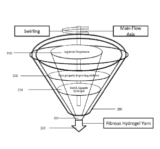
Fig. 2 illustrates a block diagram of the nozzle and the use of cross-linking
metal alginate hydrogel alongwith the fibrous suspension, according to
various embodiments of the present invention;
Fig. 3 illustrates a flow diagram for the method of selecting various raw
materials, according to various embodiments of the present invention;
Fig. 4 illustrates a block diagram of the system for producing a fibrous yarn
from various raw materials, according to various embodiments of the present
invention;
Fig. 5 illustrates a block diagram related to the system of the entire yarn
producing machine, according to various embodiments of the present
invention; and
Fig. 6 illustrates a flow diagram related to the method of the entire yarn
producing machine, according to various embodiments of the present
invention.
Like reference numerals refer to like parts throughout the description of
several views of the drawing.
DESCRIPTION OF THE INVENTION
The exemplary embodiments described herein detail for illustrative purposes
are subjected to many variations. It should be emphasized, however, that the
present invention is not limited to method and system for producing fibrous
yarn. It is understood that various omissions and substitutions of equivalents
are contemplated as circumstances may suggest or render expedient, but
CA 02983484 2017-10-20
WO 2016/174307 PCT/F12016/050269
8
these are intended to cover the application or implementation without
departing from the spirit or scope of the present invention.
Unless otherwise specified, the terms, which are used in the specification
and claims, have the meanings commonly used in the field of paper and pulp
manufacture, as well as in the field of yarn manufacture. Specifically, the
following terms have the meanings indicated below.
The terms "a" and "an" herein do not denote a limitation of quantity, but
rather
denote the presence of at least one of the referenced item.
The terms "having", "comprising", "including", and variations thereof signify
the presence of a component.
The term "fiber" refers here to raw fibrous material either produced naturally
or produced artificially.
The term "yarn" refers here to thread, yarn, chord, filament, wire, string,
rope
and strand.
The term "rheology modifier" is understood to mean here a compound or
agent capable of modifying the viscosity, yield stress, thixotropy of the
suspension.
It should be noted that the term "maximum length weighed fiber length of the
fibers" as referenced herein below means length weighted fiber length where
90 percent of fibers are shorter or equal to this length, wherein fiber length
may be measured with any suitable method used in the art.
The term "crosslinking agent" is understood to mean here a compound or
agent, such as a polymer, capable of crosslinking on fiber with itself in the
CA 02983484 2017-10-20
WO 2016/174307 PCT/F12016/050269
9
suspension. This typically takes place in the water solution phase and leads
to a gel.
The term "hydrogel" is understood to mean here a gel like composition
having plurality of solid particles suspended in a liquid phase.
The term "aqueous suspension" in the present invention is understood to
mean any suspension including water and fibers originating from any and at
least one plant based raw material source, or synthetic fiber. The plant based
raw material source including cellulose pulp, refined pulp, waste paper pulp,
peat, fruit pulp, or pulp from annual plants. The fibers may be isolated from
any cellulose containing material using chemical, mechanical, thermo-
mechanical, or chemi-thermo-mechanical pulping processes. The synthetic
fibers may comprise polyester, nylon or the like.
The term "microfibrillated cellulose", "nanofibrillar cellulose" and/or
"nanofibrillated cellulose" as used hereinafter refer to a collection of
isolated
cellulose microfibrils or microfibril bundles derived from cellulose raw
material. Microfibrils have typically high aspect ratio: the length might
exceed
one micrometer while the number-average diameter is typically below 200
nm. The diameter of microfibril bundles may also be larger but generally less
than 1 pig. The smallest microfibrils are similar to so called elementary
fibrils,
which are typically 2- 12 nm in diameter. The dimensions of the fibrils or
fibril
bundles are dependent on raw material and disintegration method.
The nanofibrillar cellulose may also contain some hemicelluloses; the amount
is dependent on the plant source. Mechanical disintegration of microfibrillar
cellulose from cellulose raw material, cellulose pulp, or refined pulp is
carried
out with suitable equipment such as a refiner, grinder, homogenizer,
colloider, friction grinder, ultrasound sonicator, fluidizer such as
microfluidizer, macrofluidizer or fluidizer-type homogenizer. In this case the
CA 02983484 2017-10-20
WO 2016/174307 PCT/F12016/050269
nanofibrillar cellulose is obtained through disintegration of plant cellulose
material and may be called "nanofibrillated cellulose".
"Nanofibrillar cellulose" may also be directly isolated from certain
5 fermentation processes. The cellulose-producing microorganism of the
present invention may be of the genus Acetobacter, Agrobacterium,
Rhizobium, Pseudomonas or Alcaligenes, preferably of the genus
Acetobacter and more preferably of the species Acetobacter xylinum or
Acetobacter pasteurianus.
"Nanofibrillar cellulose" may also be any chemically or physically modified
derivate of cellulose nanofibrils or nanofibril bundles. The chemical
modification could be based for example on carboxymethylation, oxidation,
esterification, or etherification reaction of cellulose molecules.
Modification
may also be realized by physical adsorption of anionic, cationic, or non-ionic
substances or any combination of these on cellulose surface. The described
modification may be carried out before, after, or during the production of
microfibrillar cellulose.
The nanofibrillated cellulose may be made of cellulose which is chemically
premodified to make it more labile. The starting material of this kind of
nanofibrillated cellulose is labile cellulose pulp or cellulose raw material,
which results from certain modifications of cellulose raw material or
cellulose
pulp. For example N-oxyl mediated oxidation (e.g. 2,2,6,6-tetramethyl-l-
piperidine N-oxide) leads to very labile cellulose material, which is easy to
disintegrate to microfibrillar cellulose. For example patent applications WO
09/084566 and JP 20070340371 disclose such modifications. The
nanofibrillated cellulose manufactures through this kind of premodification or
"labilization" is called "NFC-L" for short, in contrast to nanofibrillated
cellulose
which is made of not labilized or "normal" cellulose, NEC-N.
CA 02983484 2017-10-20
WO 2016/174307 PCT/F12016/050269
11
The nanofibrillated cellulose is preferably made of plant material where the
nanofibrils may be obtained from secondary cell walls. One abundant source
is wood fibers. The nanofibrillated cellulose is manufactured by
homogenizing wood-derived fibrous raw material, which may be chemical
pulp. When NFC-L is manufactured from wood fibers, the cellulose is
labilized by oxidation before the disintegration to nanofibrils. The
disintegration in some of the above-mentioned equipment produces
nanofibrils which have the diameter of only some nanometers, which is 50
nm at the most and gives a clear dispersion in water. The nanofibrils may be
.. reduced to size where the diameter of most of the fibrils is in the range
of
only 2-20 nm only. The fibrils originating in secondary cell walls are
essentially crystalline with degree of crystallinity of at least 55 %.
Embodiments of the present invention provide an aqueous solution
.. suspension by mixing raw fibrous material with additives and then adding
foam in such mixture. Thereafter, the said aqueous solution suspension is
administered from the side of a nozzle and the aqueous sol suspension start
to swirl around a main flow axis of the nozzle. Due to the gravitational pull,
an
aqueous fibrous yarn product comes out from an exit of the nozzle. Also fluid
.. pressure may be used to eject the fibrous gel yarn from the nozzle in some
embodiments. Further a wire may also be used to pull the yarn from the
nozlle, wherein the speed differential between the gel yarn and the wire is
sometimes used to induce the exit of the gel yarn from the nozzle. At the exit
of the nozzle the said aqueous fibrous yarn suspension is merged with a
.. crosslinking agent and as a result of cross-linking reaction a hydrogel is
created, such as a metal alginate hydrogel. Specifically, the said metal
alginate hydrogel is coated on the surface of the said aqueous fibrous yam
product.
.. Thereafter, the aqueous fibrous yarn product coated with the metal alginate
hydrogel is subjected to twisting, drying and dewatering process. The drying
CA 02983484 2017-10-20
WO 2016/174307 PCT/F12016/050269
12
may include methods based on vacuum, mechanical pressing and/or thermal
drying. The dewatering may be carried out by methods utilizing vacuum,
mechanical pressing, convection, conduction or radiation of heat, by any
suitable heating means such as heated airflow, IR, or contact with heated
surface.
In an embodiment, the fibrous yarn is dewatered by using the mechanical
pressing method. The mechanical pressing method as proposed by the
present invention includes a plurality of plates floating on a deformable
base.
The plurality of plates floating on a deformable base is adapted to dewater
the fibrous yarn without any wear and tear to the final yarn product. When
the fibrous yarn passes through these pluralities of floating plates only
pressure required for dewatering the fibrous yarn is applied. Accordingly, the
use of minimum pressure during dewatering process is helpful to produce a
yarn product having suitable thickness as well as a uniform structure. After
the dewatering process, the yarn is dried and the dry yarn product is
obtained.
Figures 1-6 describe the novel and inventive aspects related to the method,
system and the yarn of the present invention. The novel and inventive
aspects as illustrated in the drawings may be read in conjugation to the
claims of the present invention.
Figure 1 provides one suitable embodiment for preparing the metal alginate
hydrogel of the present invention. Firstly, the alginate is derived naturally
from the brown algae polysaccharides as per step 102. Then a solution of
such naturally extracted alginate is formed as per step 104. Thereafter, the
metal alginate hydrogel is formed by adding bivalent metal cations to such
alginate solution as per step 106. Further, yarn property enhancing additive
is
added to such metal alginate hydrogel as per step 108. Moreover, the
properties of said metal alginate hydrogel are adjusted as per the
CA 02983484 2017-10-20
WO 2016/174307 PCT/F12016/050269
13
requirement of the yarn product as per step 110. Finally, at the exit of the
nozzle the fibrous yarn is coated with such metal alginate hydrogel as per
step 112.
The tailored metal alginate hydrogel coating over the surface of the said
fibrous yarn will enable the successful delivery of the fibrous yarn in to the
drying section and protects the fibrous yarn from breakage during the twisting
and dewatering process. In addition to the fibers, also other materials that
improve the properties of the fibrous yarn, can be found in the metal alginate
.. hydrogel matrix. Finally, the said aqueous fibrous yarn product is
subjected to
twisting, drying and dewatering process.
Specifically, the coating of the metal alginate hydrogel over the surface of
the
aqueous fibrous yarn product provides a means of crosslinking the fibers.
.. Accordingly, this crosslinking of fibers provides a fibrous yarn product
with
enhanced strength and stretch and thus the breakage of the yarn could be
avoided during the twisting and the dewatering processes.
Preferably, the metal alginate hydrogel as provided herein includes alginate
as naturally derived from brown algae polysaccharides and then forming an
aqueous solution of such alginate. The structure of the alginate is an
unbranched polysaccharide consisting of nnannuronic acid (M) and guluronic
acid (G). When cations such as bivalent metal cations are added to a solution
of alginate, a metal alginate hydrogel having a cross-linked structure is
.. formed. The properties of the cross-linked structure of the said metal
alginate
hydrogel depend on following factors such as:
- biopolymer selection i.e. alginate, guar gum, pectin etc.;
- solubility of biopolymer to water;
- reactivity (cross-linking density and speed) of the
biopolymer with the metal ions;
CA 02983484 2017-10-20
WO 2016/174307 PCT/F12016/050269
14
- control of the metal alginate hydrogel swelling/shrinking
(pH) to control the release of water from the metal
alginate hydrogel matrix.
In the presence of metal cations, particularly divalent or multivalent cations
(cross linking reagent), suitably such as Ca2+, Al2+. Na2+. Mg2+, Sr2+ or
Ba2+, (cross linking agent), alginate, pectin and carrageenan (carrageenan
cross-links also with K+) readily form a stable and strong gel. In the cross-
linking of these polysaccharides calcium chloride is preferably used. The
concentration of salt solution may vary from 1% w/w to 10% w/w.
Typically the poly-L-guluronic acid (G-block) content of alginate, poly-D-
galacturonic acid content of pectin or carrageenan and the amount of divalent
or multivalent cations (calcium ions) are regarded as being involved in
determining gel strength.
Figure 2 provides the block diagram for the nozzle adapted to produce the
yarn in conjugation with the cross-linking of suspension by the metal alginate
hydrogel.
In various embodiments of the present invention, it was surprisingly found
that fibrous yarn may be manufactured in a very simple and efficient way
directly from a fibrous suspension, whereby it is not necessary to
manufacture first paper or other fibrous product, which is sliced into strips
and wound to a yarn.
It will be understood by the person skilled in the art that in the process for
manufacturing of fibrous yarn, a suspension is usually directed through a
nozzle and thereafter the fibrous yarn is dewatered. One way of
manufacturing such fibrous yarn has been disclosed in WO publication
number WO 2013/034814 Al. Suitably the amount of nozzles required in the
WO 2016/174307 PCT/F12016/050269
system is selected depending upon the manufacturing equipment used and
on the product which is manufactured.
Usually, any nozzle or extruder suitable for liquids and viscous fluids may be
5 used in such system. When the suspension contains alginates, pectin or
carrageenan, suitably a nozzle is used including an inner die or orifice for
the
suspension and outer die or orifice for an aqueous solution comprising at
least one cation. Cation may comprise a salt, such as calcium chloride or
magnesium sulphite. Alternatively, the solution comprising the cation (salt)
10 may be provided as a spray or mist when using nozzles with one orifice.
The
cation, when brought in contact with for example with alginate or alginic
acid,
provides effect of very rapid increase on the viscosity of the aqueous
suspension whereby the strength of the yarn is increased, making the
embodiment of the method utilizing the gravitational force very attractive.
Moreover, the inner diameter of the outlet of the nozzle is kept smaller than
or equal to the maximum length weighed fiber length of the fibers. This helps
to orientate the fibers essentially in the direction of the yarn and provides
strength and flexibility to the product.
The nozzle of the present invention is specially designed. This specially
designed nozzle has been disclosed in cross-referenced patent application
number 62/153,635 titled "MECHANICAL METHOD AND SYSTEM FOR
THE MANUFACTURE OF FIBROUS YARN" from the same inventors.
Now referring to figure 2, a nozzle 200 has been provided, wherein the
aqueous suspension 210 is directed from the side of the nozzle and the
aqueous suspension is allowed to swirl around the main flow axis of the
Date Recue/Date Received 2021-10-12
CA 02983484 2017-10-20
WO 2016/174307 PCT/F12016/050269
16
nozzle. Further, yarn property improving additives 220 are added to the
aqueous suspension. The aqueous suspension includes raw fibrous material
mixed with foam material. At the exit 201 of the nozzle 200, the aqueous
fibrous yarn is merged with the annular flow of the metal alginate hydrogel
230.
Further, the present invention provides a mechanism by which the fibrous
yarn is simultaneously pulled and twisted while the aqueous suspension
(210) flows through the exit of the nozzle (200). Such pulling and twisting of
the fibrous yarn increases the strength and stretch of the final yarn product.
After exiting the nozzle (200) the aqueous yarn suspension is subjected to
dewatering and drying.
In various embodiments, the nozzle (200) is adapted to swirl the flow of the
aqueous suspension (210) around a main flow axis of the said nozzle (200).
In another embodiment, the aqueous suspension (210) is allowed to swirl
around the main flow axis of the at least one nozzle (200) by feeding the
aqueous suspension asymmetrically from the side of the said nozzle (200).
In another embodiment, the nozzle (200) is designed such that aqueous
suspension (210) is allowed to swirl around the main flow axis of the at least
one nozzle by creating, rotating and accelerating a flow of the aqueous
suspension, where all the fibers are well aligned with the said flow by
rotating
around the main flow axis.
In another embodiment, the nozzle (200) is such that aqueous suspension
(210) is allowed to swirl around the main flow axis of the at least one nozzle
by creating a swirling flow through a plurality of grooved flow channels.
.. In various embodiments, the aqueous suspension (210) is allowed to swirl
around the main flow axis of the at least one nozzle (200) by creating a
CA 02983484 2017-10-20
WO 2016/174307 PCT/F12016/050269
17
swirling flow through a plurality of bend flow channels. The bend flow
channels may comprise ninety degree bend flow channels.
In another embodiment, the annular flow of the metal alginate hydrogel is
adapted to combine a plurality of fibrous yarns through a plurality of annular
flow channels. The pluralities of fibrous yarns are combined by using a
plurality of small nozzles directed radially inside the annular flow of the
metal
alginate hydrogel.
The plurality of annular flow channels, as referenced above, include an
innermost annular flow channel, an outermost annular flow channel, and an
annular flow channel sandwiched between the innermost annular flow
channel and the outermost annular flow channel.
In various embodiments, the innermost annular flow channel is adapted to
accommodate the fiber suspension and the rheology modifier. The outermost
annular flow channel is adapted to accommodate the metal alginate
hydrogel. The sandwiched annular flow channel is adapted to accommodate
the yarn property improving additives.
Accordingly, the final yarn product thus produced by the above method
possesses improved yarn strength as well as improved yarn diameter. The
swirling of the aqueous suspension around the main flow axis of the nozzle
and treating the suspension with metal alginate hydrogel as well as yarn
property improving additives through the plurality of annular flow channels
produces a fibrous yam having improved strength and diameter.
Figure 3 provides a flow diagram for the method for selecting raw materials.
Further, figure 4 provides a block diagram for the method for selecting raw
materials.
CA 02983484 2017-10-20
WO 2016/174307 PCT/F12016/050269
18
Firstly, raw fibrous material is selected from natural fibers or synthetic
fibers
as per step 302. Then additives such as microfibrillated cellulose or clay
(e.g.
bentonite, montmorillonite) are added to the raw fibrous material as per step
304 and 306. Further, some conductive material such as activated carbon is
added in the raw fibrous material as per step 308. Further, an aqueous
suspension is prepared by adding foam to such raw fibrous material as per
step 310. Finally the yarn with the higher strength and stretch properties is
produced as per step 312.
The natural fibers as provided herein are selected from the plant based raw
material source which may be a virgin source or recycled source or any
combination thereof. It may be wood or non-wood material. The wood may
be softwood tree such as spruce, pine, fir, larch, douglas-fir or hemlock, or
hardwood tree such as birch, aspen, poplar, alder, eucalyptus or acacia, or a
mixture of softwoods and hardwoods. The non-wood material may be plant,
such as straw, leaves, bark, seeds, hulls, flowers, vegetables or fruits from
corn, cotton, wheat, oat, rye, barley, rice, flax, hemp, manilla hemp, sisal
hemp, jute, ramie, kenaf, bagasse, bamboo, reed or peat.
Suitably virgin fibers originating from pine may also be used. Said fibers
typically may have average length weighed fiber length from 2 to 3
millimeters. Also combinations of longer fibers with shorter ones may be
used, for example fibers from pine with fibers from eucalyptus.
The aqueous suspension as provided herein may optionally comprise virgin
or recycled fibers originating from synthetic materials, such as glass fibers,
polymeric fibers, metal fibers, or from natural materials, such as wool
fibers,
or silk fibers.
CA 02983484 2017-10-20
WO 2016/174307 PCT/F12016/050269
19
The aqueous suspension as provided herein may comprise from 0.1 to 10
percent CYO weight/weight (w/w), preferably from 0.2 to 5% w/w of fibers
originating from any plant based raw material source.
Preferably, in embodiments of the present invention the aqueous suspension
may be in the form of foam. In that case the suspension includes at least one
surfactant selected from anionic surfactants and non-ionic surfactants and
any combinations thereof, typically in an amount of from 0.001 to 1% w/w.
The aqueous suspension may include at least one rheology modifier that
forms a gel by crosslinking the aqueous suspension, The rheology modifier
may be selected from alginic acid, alginates such as sodium alginate, pectin,
carrageenan, and nanofibrillar cellulose (NFC), or a combination of rheology
modifiers.
Preferably, the rheology modifier may be an additive added to improve the
properties of the final yarn product. Such additives are selected from the
group of components including montmorillonite, polyester, nylon, metals,
ions, any electrically conductive material and/or activated carbon.
Said rheology modifier may be used in an amount from 0.1 to 20 weight `)/0.
Concentration of the rheology modifier, such as alginate is preferably 0.5 -
20
% w/w.
The aqueous suspension as provided herein may also include at least one
dispersion agent that is typically anionic long chained polymer or NFC, or a
combination of dispersion agents. Examples of suitable dispersion agents are
carboxymethyl cellulose (CMC), starch (anionic or neutral) and anionic
polyacrylamides (APAM), having high molecular weight. Dispersion agent
modifies the suspension rheology to make the suspension shear thinning.
CA 02983484 2017-10-20
WO 2016/174307 PCT/F12016/050269
Preferably at high shear rates (500 1/s) shear viscosity is less than 10% of
zero shear viscosity of the suspension.
Said dispersion agent may be used in an amount from 0.1 to 20 weight %.
5
The aqueous suspension as provided herein may be obtained using any
suitable mixing method known in the art.
Moist yarn having metal alginate hydrogel coating as obtained from the
10 nozzle (at step 312) initially contains water typically from 30 to 99.5%
w/w. In
the dewatering step the yarn may be dried to desired water content.
Accordingly, the fibrous yarn in the form of gel exiting from the nozzle is
subjected to the dewatering and twisting process.
15 In addition and with reference to the aforementioned, embodiments of the
invention comprise the aqueous suspension having fibers and at least one
rheology modifier is allowed to swirl around the main flow axis of the nozzle.
Such swirling of the aqueous suspension around the main flow axis of the
nozzle is completed by feeding the aqueous suspension asymmetrically from
20 the side of the nozzle. Further, yarn property improving additives is
also
added to the aqueous suspension. Furthermore, a metal alginate hydrogel is
merged with the flow of the aqueous suspension at the exit of the nozzle.
Moreover, the aqueous suspension at the exit of the nozzle is pulled and
twisted and then subjected to pressing and dewatering process.
The dewatering and twisting of the yarn is facilitated using dewatering
apparatus (580) as shown in Figures 5-6, which is now explained.
The fibrous gel yarn at the exit of the nozzle, such as nozzle (200), is
dropped on a conveyer system (560) having a conveyer belt (550) [also
referred as wire (550) or base wire (550)] operating on rollers (552) and
CA 02983484 2017-10-20
WO 2016/174307 PCT/F12016/050269
21
(554). Due to the movement of the conveyer system (560), the fibrous gel
yarn is pulled in the dewatering apparatus (580).
Thereafter, the pulled fibrous gel yarn is subjected to pre-pressing through a
pressing plate, such as pressing plate (505) and roller (504) assembled for
that purpose, at step 608. Thereafter, at step 610, the fibrous gel yarn is
passed through a plurality of plates, such as plates (510), in Figure 5. The
floating plates (510) are floating on a deformable base (520). In one
embodiment, the floating plates (510) are floating over a stationary base
(520).
The floating plates (510) and the deformable/ stationary base (520) are
supported by a conveyer system having plurality of rollers (516) running a
conveyer belt (518) [also referred as wire (518) or upper wire (518)1. This
system allows pulling and twisting of the fibrous yarn in the dewatering
apparatus (580).
The plurality of floating plates (510) applies suitable pressure as required
for
the dewatering of the fibrous gel yarn, at step 610. Further, the plurality of
floating plates (510) is adapted to twist and dewater the fibrous gel yarn for
dewatering at step 612. Moreover, the floating plates (510) are adapted to
maintain the uniform round shape of the yarn during the dewatering phase
and give a good tensile strength to the final yarn product at step 614.
Figures 5 and 6 provide block diagram and flow chart respectively for the
system of the entire yarn producing apparatus (500) as proposed by the
present invention. The system includes an aqueous suspension having fibers
and at least one rheology modifier, fed in the nozzle (200). The system
further includes the dewatering apparatus (580). The nozzle (200) is adapted
to arrange a swirling flow of the aqueous suspension. The system further
includes a pressing mechanism having the conveyer system (560) with
CA 02983484 2017-10-20
WO 2016/174307 PCT/F12016/050269
22
rollers (552), (554) and belt, which pulls the fibrous gel in the dewatering
apparatus (580).
The dewatering apparatus (580) includes pre-pressing roller (504) and plate
(505) which pre-presses the yarn to dehydrate it, and floating plates (510)
supported on stationary/ floating base (520), which twists the yarn.
Figure 6 specifically illustrates a flow diagram explaining operation of yarn
producing apparatus. The aqueous suspension having fibers and foam along
with yarn property improving additives are fed from the nozzle (200). In one
embodiment, they may be fed from the side of the nozzle, such as nozzle
(200), at step 602. The nozzle (200) is adapted to swirl the flow of the
aqueous suspension along the main flow axis of the nozzle, at step 604.
Then at the exit of the nozzle, the aqueous suspension pulled and twisted
and merged with the annular flow of a metal alginate hydrogel, at step 606.
Then fibrous gel yarn at the exit of the nozzle is subjected to the dewatering
process as explained hereinabove.
It should be noted that any features, steps, phases or parts of embodiments
as hereinabove disclosed can be freely permuted and combined with each
other in a combination of two or more embodiments in accordance with the
invention.
The invention provides several advantages. The manufacturing method is
very simple and effective, and the equipment needed is simple and relatively
cheap. The yarn is produced directly from the fiber suspension and it is not
necessary to manufacture first paper strips.
The rheology of the fiber suspension may be adjusted using rheology
modifiers to the viscosity and thixotropy range where the fiber suspension
can be pumped through the nozzle without clogging it, but simultaneously to
CA 02983484 2017-10-20
WO 2016/174307 PCT/F12016/050269
23
provide a moist yarn typically in gel form, which has sufficient strength to
maintain its form during the drying step. Thus the rheology modifier gives
shear thinning nature and strength to the yarn; in the case alginate is used a
dispersion agent is typically also needed and the treatment of the moist yarn
with a salt solution to provide sufficient strength. The selection of the
inner
diameter of the outlet of the nozzle to smaller than or equal to the maximum
length weighed fiber length of the fibers achieves the fibers to orientate in
the
direction of the yarn, which provides the final product flexibility and
strength.
The water released after drying may be recovered by condensing and
recycled in the method, for example by using a closed system, and thus
practically no wastewater is formed. Also the amount of water needed in the
process is very limited, particularly in the embodiment where the fiber
suspension is provided in the form of foam.
The product is completely biodegradable when the starting materials used
are natural materials.
The need of cotton may be reduced with the method and products of the
present invention, where the fibers originate at least partly from more
ecological plant material, such as wood and recycled paper.
Particularly, long fiber pulp, suitably manufactured from Nordic pine, may be
used in the method to provide a yarn having the thickness of less than 0.1
mm and very good strength properties.
While the invention has been described with respect to specific examples
presented in the figures, including presently preferred modes of carrying out
the invention, those skilled in the art will appreciate that there are
numerous
variations and permutations of the above described embodiments that fall
within the spirit and scope of the invention. It should be understood that the
CA 02983484 2017-10-20
WO 2016/174307 PCT/F12016/050269
24
invention is not limited in its application to the details of construction and
arrangements of the components set forth herein. Variations and
modifications of the foregoing are within the scope of the present invention.
Accordingly, many variations of these embodiments are envisaged within the
scope of the present invention.
The foregoing descriptions of specific embodiments of the present invention
have been presented for purposes of illustration and description. They are
not intended to be exhaustive or to limit the present invention to the precise
forms disclosed, and obviously many modifications and variations are
possible in light of the above teaching. The embodiments were chosen and
described in order to explain the principles of the present invention and its
practical application, and to thereby enable others skilled in the art to
utilize
the present invention and various embodiments with various modifications as
are suited to the particular use contemplated. It is understood that various
omissions and substitutions of equivalents are contemplated as
circumstances may suggest or render expedient, but such omissions and
substitutions are intended to cover the application or implementation without
departing from the spirit or scope of the present invention.